Laser welding method for large-gap weld

A laser welding, large gap technology, applied in laser welding equipment, welding equipment, metal processing equipment and other directions, can solve the problem of complex welding methods

Inactive Publication Date: 2015-10-28
HANS LASER TECH IND GRP CO LTD
View PDF5 Cites 25 Cited by
  • Summary
  • Abstract
  • Description
  • Claims
  • Application Information

AI Technical Summary

Problems solved by technology

[0003] The purpose of the embodiments of the present invention is to provide a laser welding method for large gap welds to solve the problem of complicated welding methods

Method used


Image

  • Laser welding method for large-gap weld
  • Laser welding method for large-gap weld
  • Laser welding method for large-gap weld

Examples


Embodiment Construction

[0021] In order to make the object, technical solution and advantages of the present invention clearer, the present invention will be further described in detail below in conjunction with the accompanying drawings and embodiments. It should be understood that the specific embodiments described here are only used to explain the present invention, not to limit the present invention.

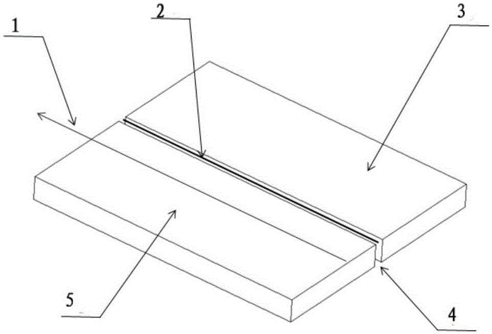
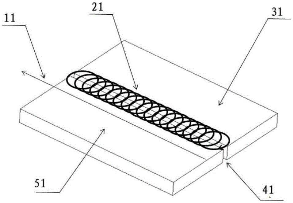
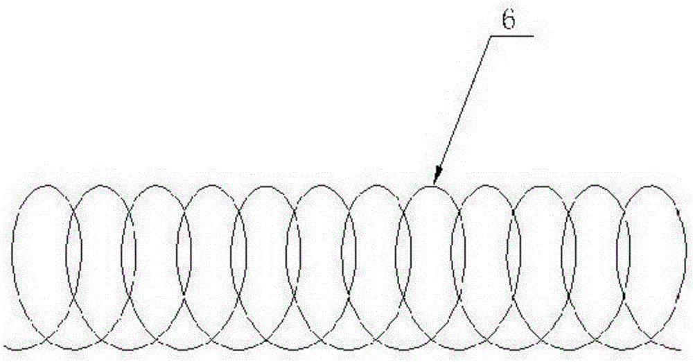
[0022] An embodiment of the present invention provides a laser welding method for large gap welds. For workpieces to be welded with large gaps, the laser scans the welding area of ​​the workpiece to be welded according to a reciprocating trajectory or a superimposed trajectory, so that the laser irradiation range increases and realizes Laser direct welding of large gap welds. If two workpieces to be welded are placed adjacent to each other to form a large gap weld, the laser directly scans the workpiece to be welded at the large gap weld according to a reciprocating or superimposed trajectory.

[...


PUM


Abstract

The invention is suitable to be used for the field of laser welding, and provides a laser welding method for large-gap welds. Through reciprocating tracks or overlaying tracks, laser welding is performed, and additional solder or heat resource (composite welding energy source) is not needed. The method increases laser irradiation range just through changing welding paths (that is, laser irradiation paths) of laser, so as to increase melting area and melting quantity of a welding pool, improve tolerance of welding gaps, and increase applicability and convenience for laser welding.

Description

technical field [0001] The invention belongs to the field of laser welding, in particular to a laser welding method for large-gap welds. Background technique [0002] Laser welding is a high-energy density and high-precision processing method, which has poor tolerance to gaps, so it requires high matching accuracy of the welded workpieces. Excessive welding gaps will cause more poor welding, or even failure to weld. General technical means usually use methods that are not sensitive to gaps, such as adding solder or using laser hybrid welding, etc., such as figure 1 As shown, there is a large gap 4 between the workpieces 3 and 5 to be welded. Hybrid welding or filler welding is used to weld along the welding direction 1 and adopt a linear trajectory 2 to form a weld, but the technology is complicated, the equipment is expensive, and it is convenient. Poor sex. Contents of the invention [0003] The purpose of the embodiments of the present invention is to provide a laser ...

Claims


Application Information

Patent Timeline
Patent Type & Authority Applications(China)
IPC IPC(8): B23K26/24B23K26/082
CPCB23K26/24
Inventor 朱宝华肖华高云峰
Owner HANS LASER TECH IND GRP CO LTD
Why Eureka
Try Eureka