Special grinding machine for in-situ grinding of pinch roller of shearing machine

A special grinding machine and pinch roller technology, which is applied in the direction of grinding machines, machine tools designed for grinding the rotating surface of workpieces, grinding/polishing equipment, etc., can solve the wear deformation, adhesion, and thermal fatigue of the outer surface of the pinch roller and other problems, to achieve the effect of grinding and dressing, high positioning accuracy and high processing accuracy

Active Publication Date: 2017-07-28
XIAN UNIV OF TECH
View PDF4 Cites 0 Cited by
  • Summary
  • Abstract
  • Description
  • Claims
  • Application Information

AI Technical Summary

Problems solved by technology

[0003] When the pinch roller clamps and conveys the steel plate, the roller body bears a large bending moment, and the roller surface bears a large contact stress, which is easy to cause deformation of the pinch roller or wear of the roller surface
Due to the large number of pinch rollers used in the shearing machine, the cost is high, and the replacement cycle is relatively long. Generally, the rollers are removed for surface grinding and repair or replacement during overhaul (because the pinch rollers are very heavy, during loading and unloading or replacement) Labor intensity is high), so the pinch roller is required to have high wear resistance and service life; in addition, the maximum temperature of the pinch roller is about 600°C when it is working, and it needs to be continuously cooled by water, which leads to cold and heat fatigue; at the same time, due to the pinch roller The plastic flow on the surface of the roller and the mutual movement of the strip will cause material adhesion, and the long-term transfer contact wear between the pinch roller and the tangential surface of the steel plate will cause wear and deformation (elliptical shape, conical shape) on the outer surface of the pinch roller. Thus affecting the clamping and transmission performance of the pinch roller to the workpiece steel plate, and then affecting the shearing efficiency and shearing accuracy of the shearing machine

Method used


Image

  • Special grinding machine for in-situ grinding of pinch roller of shearing machine
  • Special grinding machine for in-situ grinding of pinch roller of shearing machine
  • Special grinding machine for in-situ grinding of pinch roller of shearing machine

Examples


Embodiment Construction

[0026] The present invention will be described in detail below in conjunction with the accompanying drawings and specific embodiments.

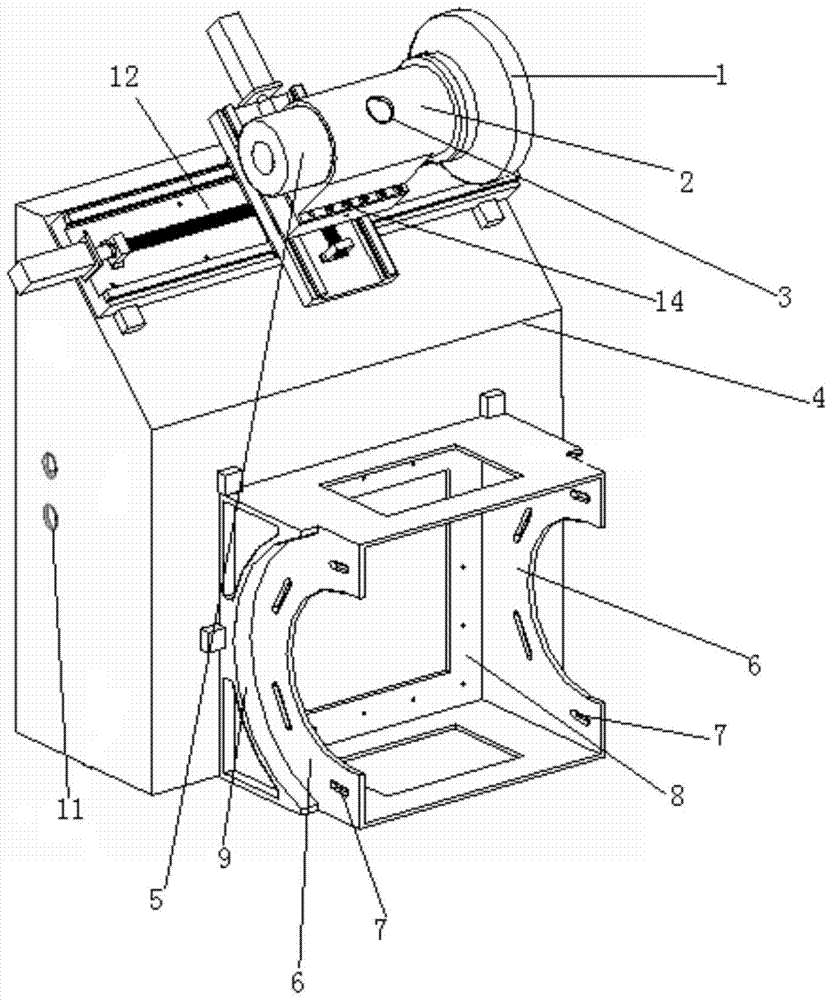
[0027] The special grinding machine for in-position grinding of the outer circle of the pinch roller of the shearing machine of the present invention has a structure such as figure 1 As shown, it includes a right-angled trapezoidal block-shaped bed 4, a cross slide 12 is arranged close to the inclined surface of the bed 4, an adjustment block 14 is provided on the workbench of the cross slide 12, and a grinding mechanism is installed on the adjustment block 14 , the upper bottom surface of the bed 4 is provided with a pinch roller fixing frame, and the pinch roller fixing frame is provided with a threaded groove 7 for fixing the pinch roller, the cross slide 12 is parallel to the inclined plane of the bed 4, and the pinch roller fixing frame It is located at the center of the bed 4 upper bottom.

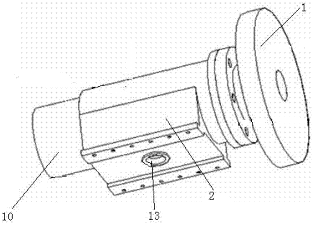
[0028] Such as figure 2 As shown, the grin...


PUM


Abstract

The invention discloses a special grinding machine for in situ grinding cylindrical surfaces of pinch rolls of a plate shearing machine. The special grinding machine comprises a machine body in a right-angled trapezoid block shape; a cross-shaped sliding table is closely arranged on the oblique plane of the machine body; a regulating block is arranged on the work table of the cross-shaped sliding table; a grinding mechanism is mounted on the regulating block; a pinch-roll fixing frame is arranged on the upper bottom surface of the machine body; thread grooves for fixing pinch rolls are formed in the pinch-roll fixing frame. The grinding machine is compact in structure, easy to assemble and disassemble, high in positioning precision, light in weight, and convenient to carry, and has the advantages of being flexible in processing, easy to control, high in processing precision, and the like; the grinding machine can grind large-sized workpieces, and can realize the in-situ grinding and trimming of cylindrical surfaces of pinch rolls under the premise that the grinding precision of the surfaces of pinch rolls is guaranteed.

Description

technical field [0001] The invention belongs to the technical field of numerical control machine tool manufacturing, and relates to a special grinding machine for in-situ grinding of pinch rollers of plate shears. Background technique [0002] The roll-cut double-sided shear is an important online production equipment on the finishing line of the rolling mill. It consists of two edge-trimming shears, one of which is fixed, and the other is movable and can be adjusted according to the width of the steel plate. There are two pairs of upper and lower pairs of pinch rollers at the front and rear of the two shears, which are used for conveying and clamping the steel plate to be processed during shearing. At the beginning of shearing, the steel plate is clamped by two pairs of pinch rollers at the entrance, and at the same time, the steel plate is advanced for a certain distance according to the setting. At the exit pinch roller, the two pairs of exit pinch rollers are also clamp...

Claims


Application Information

Patent Timeline
Patent Type & Authority Patents(China)
IPC IPC(8): B24B5/36B24B5/16
CPCB24B5/167B24B5/363
Inventor 高峰王卓李艳韩亚妮张东亚
Owner XIAN UNIV OF TECH
Why Eureka
Try Eureka