
Burner for gas water heater

A technology for gas water heaters and burners, which is applied in the direction of gas fuel burners, burners, and combustion methods. It can solve the problems of unsatisfactory increase in combustion degree, unimproved air supply and mixing uniformity, and reduce emissions. Quantity, ensuring adequacy and thoroughness, and high combustion efficiency

Active Publication Date: 2015-10-28
NINGBO FOTILE KITCHEN WARE CO LTD
View PDF6 Cites 3 Cited by
  • Summary
  • Abstract
  • Description
  • Claims
  • Application Information

AI Technical Summary

Problems solved by technology

The burner is effective in avoiding flashback by changing the structure of the fire hole, but its two factors of air supply and mixing uniformity have not been improved, and these two factors are the key factors restricting the combustion performance of the burner. Therefore, The increase in burn rate is not ideal

Method used


Image

  • Burner for gas water heater
  • Burner for gas water heater
  • Burner for gas water heater

Examples


Embodiment Construction

[0024] The present invention will be further described in detail below in conjunction with the accompanying drawings and embodiments.

[0025] Such as Figure 1 to Figure 7 As shown, the burner for gas water heater includes:

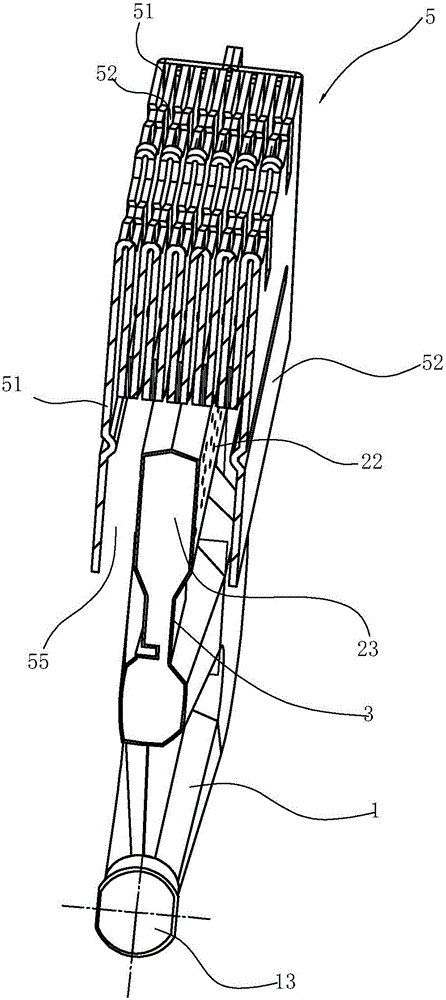
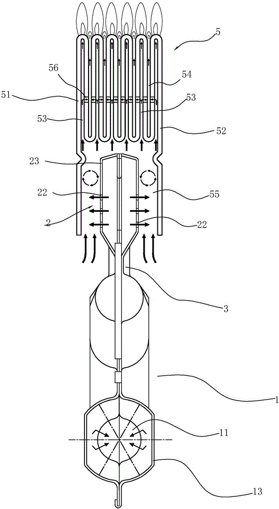
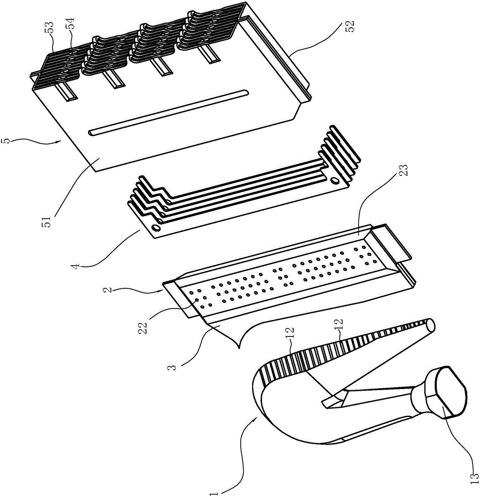
[0026] Injection pipe 1 is used to initially mix the air and gas entering it, and any structure in the prior art can be selected according to needs. The ejector tube in this embodiment is a hollow tubular structure in a lying "U" structure, and its air inlet 11 is located on the port of the pipe below the ejector tube, and the port is also connected with a horn for easy air intake Port 13; the port of the upper pipeline of the ejector tube is closed, and the gas outlet 12 of the ejector tube is arranged on the side wall of the upper pipeline.

[0027] The air box 2 includes a box body 23 , and the box body 23 is provided with an air inlet and an air outlet 22 . There are multiple air outlets 22 of the air box 2, which are evenly distributed on the two...


PUM


Abstract

The invention relates to a burner for a gas water heater. The burner comprises an injecting pipe and a burning head. The burner is characterized in that an outlet of the injecting pipe is connected with the inner cavity of a gas box in a sealing manner, and a plurality of gas outlets are formed in the lateral wall of the gas box; the burning head comprises a first baffle and a second baffle, and a plurality of gas flow passages and a plurality of overflow passages, which are sequentially and alternately arranged in parallel, are arranged between the first baffle and the second baffle; a cavity with an openmouthed lower end for accommodating the gas box is formed between the first baffle and the second baffle under the gas flow passages and the overflow passages, the upper end and the lower end of each of the gas flow passages are opened, the lower opening of each of the gas flow passages is communicated with the cavity, an overflow hole communicated with the adjacent overflow passage is formed in the lateral wall of each of the gas flow passages, the lower ends of the overflow passages are closed, and the upper ends of the overflow passages are opened; the gas box is accommodated in the cavity, and gaps are formed between the gas box and the first baffle and between the gas box and the second baffle.

Description

technical field [0001] The invention relates to a burner, in particular to a burner for a gas water heater. Background technique [0002] A burner is a device that converts substances into heat energy through the chemical reaction of combustion, that is, air and fuel are mixed through a premixing device and then burned. Burners are divided into oil burners, gas burners and dual fuel burners according to the dyes they burn. Among them, gas burners are the most widely used in civilian use. [0003] The key part of the burner is the combustion chamber, where the gas and air are mixed, and the gas reacts with the oxygen in the air to generate heat energy for heating. [0004] Existing burners usually use a certain amount of air brought in during the gas flow transmission process. Due to insufficient air mixing, there are problems of unstable combustion, low combustion efficiency, and large emissions of harmful gases, especially NOx emissions. Can no longer meet the requiremen...

Claims


Application Information

Patent Timeline
IPC IPC(8): F23D14/04F23D14/46F23D14/64
CPCF23D14/04F23D14/46F23D14/64
Inventor 秦刚徐德明杜一鸣王菲谭洵沈文权朱海龙卢志龙茅忠群诸永定周高云
Owner NINGBO FOTILE KITCHEN WARE CO LTD
Learn More