Electronic cigarette lighter for automobile

A technology for automotive electronics and cigarette lighters, applied to instruments, electrical components, incandescent ignition, etc., can solve the problems of short heating time, poor effect, and low conversion efficiency, and achieve reduced manufacturing costs, high transmission efficiency, and reduced surface area Effect

Active Publication Date: 2015-10-28
KEBODA TECH CO LTD
View PDF7 Cites 4 Cited by
  • Summary
  • Abstract
  • Description
  • Claims
  • Application Information

AI Technical Summary

Problems solved by technology

Although the traditional car cigarette lighter has a simple structure, it has the following defects: 1. Since the connection between the cigarette lighter and the battery is realized by a circlip, the circlip is easily deformed as the number of times of use increases, resulting in poor cigarette lighting effect or even failure , poor durability; 2. Since the pop-up of the cigarette lighter is realized by the thermal effect of the circlip, the final heated temperature of the resistance wire is easily affected by the conditions of use and the environment; 3. The traditional cigarette lighter has poor continuous use effect , this is because the continuous use causes the circlip to be heated repeatedly and fails to return to the initial temperature, so the continuous use makes the heating time and temperature of the resistance wire not guaranteed; 4. The heating time of the traditional cigarette lighter is affected by the battery voltage. Influence, this is because the resistance value of the resistance wire is basically fixed, the battery voltage is high, the current is large, the heating time is short, the battery voltage is low, the current is small, and the heating time is long
This brings problems such as low overall conversion efficiency, high cost, and high-voltage safety hazards.

Method used


Image

  • Electronic cigarette lighter for automobile
  • Electronic cigarette lighter for automobile

Examples


Embodiment Construction

[0024] The present invention will be described in detail below in conjunction with the accompanying drawings and specific embodiments.

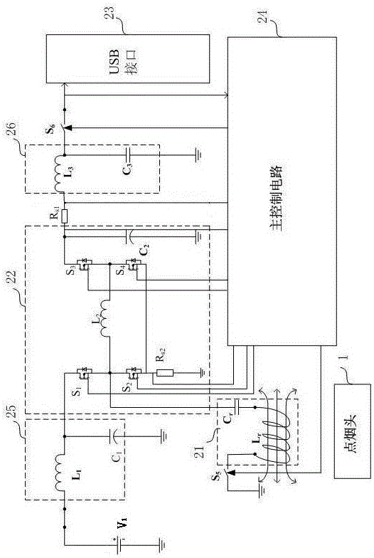
[0025] Please refer to figure 1 . According to an embodiment of the present invention, an electronic cigarette lighter for a car includes a cigarette lighting head 1 and a cigarette lighting and charging multiplexing circuit.

[0026] The cigarette lighter 1 is provided with a metal block. The cigarette lighting and charging multiplexing circuit includes an LC resonant circuit 21 , a synchronous rectification Buck-Boost circuit 22 , a USB interface 23 , a first switch circuit, a second switch circuit, an output current sampling circuit, a current-limiting current sampling circuit and a main control circuit 24 .

[0027] The LC resonant circuit includes a resonant capacitor C r and induction heating coil L r . exist figure 1 In the illustrated embodiment, the LC resonant circuit is an LC series resonant circuit. In another embodiment, t...


PUM


Abstract

The invention discloses an electronic cigarette lighter for an automobile. The electronic cigarette lighter comprises a cigarette lighting head and a cigarette lighting and charging multiplex circuit. The cigarette lighting head is provided with a metal block. The cigarette lighting and charging multiplex circuit comprises an LC resonance circuit, a synchronous rectification Buck-Boost circuit, a USB interface, a first switching circuit, a second switching circuit, an output current sampling circuit, a limited current sampling circuit and a master control circuit. The master control circuit is used for selectively enabling one of the first switching circuit and the second switching circuit to be connected. When the first switching circuit is connected, an induction heating coil of the LC resonance circuit is made to generate an alternating magnetic field, so that vortex is generated in the metal block to heat the metal block. When the second switching circuit is connected, the charging mode of equipment to be charged can be recognized, and the synchronous rectification Buck-Boost circuit is controlled to output charging voltage and charging current corresponding to the recognized charging mode. According to the electronic cigarette lighter, the cigarette lighting and charging functions can be achieved at the same time, the multiplex degree of the circuit is high, and the manufacturing cost of the electronic cigarette lighter is low.

Description

technical field [0001] The invention relates to a car cigarette lighter. Background technique [0002] The traditional car cigarette lighter heats the resistance wire by directly adding the battery voltage to the two ends of the resistance wire of the cigarette lighter, and the connection and disconnection of the cigarette lighter and the battery are realized by a spring structure. Although the traditional car cigarette lighter has a simple structure, it has the following defects: 1. Since the connection between the cigarette lighter and the battery is realized by a circlip, the circlip is easily deformed as the number of times of use increases, resulting in poor cigarette lighting effect or even failure , poor durability; 2. Since the pop-up of the cigarette lighter is realized by the thermal effect of the circlip, the final heated temperature of the resistance wire is easily affected by the conditions of use and the environment; 3. The traditional cigarette lighter has poo...

Claims


Application Information

Patent Timeline
Patent Type & Authority Applications(China)
IPC IPC(8): F23Q7/22H02M3/156
Inventor 赵俊阳彩赵国强
Owner KEBODA TECH CO LTD
Why Eureka
Try Eureka