A rotary tunnel kiln

A tunnel kiln and rotary technology, applied in the kiln field, can solve the problems of cost increase, resource consumption, and easy production of defective products, and achieve the effects of uniform temperature distribution, reduced heating frequency, and improved product quality

Active Publication Date: 2017-01-18
FUJIAN WILL CERAMIC CO LTD
View PDF1 Cites 0 Cited by
  • Summary
  • Abstract
  • Description
  • Claims
  • Application Information

AI Technical Summary

Problems solved by technology

[0003] The problem that usually exists in the use of existing tunnel kilns is that the heat distribution is uneven, which is usually manifested by the fact that the heat flows upward under the action of the air flow or the nature of the heat itself easily flows upwards, resulting in a temperature difference between the upper and lower parts of the kiln or the two side walls. , which affects the strict temperature requirements of the firing or decal steps of ceramic products in the production process, and is prone to produce defective products. The loss of heat between the two causes waste of fuel, consumes resources and increases costs, and the energy-saving effect is not good.

Method used


Image

  • A rotary tunnel kiln
  • A rotary tunnel kiln
  • A rotary tunnel kiln

Examples


Embodiment 1

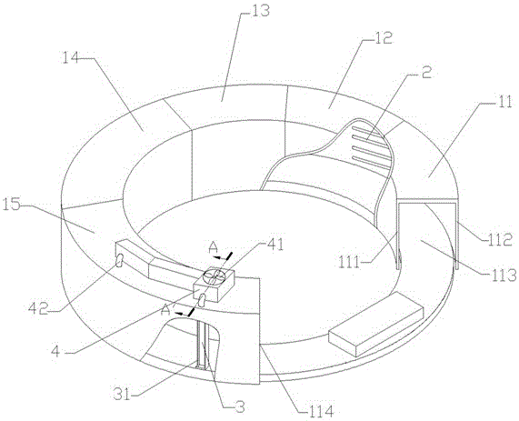
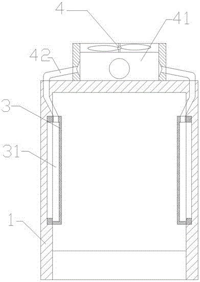
[0021] refer to figure 1 , figure 2 , image 3 and Figure 4 , a rotary tunnel kiln, comprising an annular kiln body 1 composed of an inner wall 111 and an outer wall 112 and a track arranged at the inner bottom of the kiln body 1, one end of the kiln body 1 is a feed inlet 113, and the other end is an outlet Material opening 114, the inside of the kiln body 1 is a drying chamber 11, a primary oxidation chamber 12, a secondary oxidation chamber 13, a firing chamber 14 and a cooling chamber 15 in sequence from the feed inlet 113 to the discharge outlet 114. The two side walls of each kiln chamber in the kiln body 1 except the cooling chamber 15 are provided with six spiral iron-chromium-aluminum heating wires 2 of the same specification from top to bottom, and the power of the heating wires in the drying chamber 11 is 42kw , the power of the heating wire in the primary oxidation chamber 12 is 60kw, the power of the heating wire in the secondary oxidation chamber 13 is 80kw,...

Embodiment 2

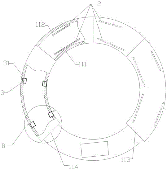
[0023] refer to Figure 5 , a rotary tunnel kiln, comprising an annular kiln body 1 composed of an inner wall 111 and an outer wall 112 and a track arranged at the inner bottom of the kiln body 1, one end of the kiln body 1 is a feed inlet 113, and the other end is an outlet Material port 114, the inside of the kiln body 1 is a drying chamber 11, a primary oxidation chamber 12, a secondary oxygen chamber 13, a firing chamber 14 and a cooling chamber 15 in sequence from the feed port 113 to the discharge port 114. The two side walls of each kiln chamber except the cooling chamber 15 in the kiln body 1 are provided with six helical iron-chromium-aluminum heating wires 2 of the same specification from top to bottom, and the heating wires on the side walls of the firing chamber are connected to the The length ratio of the heating wires on the inner wall is 0.9:1. The spiral iron-chromium-aluminum heating wires 2 in each kiln chamber are connected to the same circuit and controlled...


PUM


Abstract

The invention relates to a kiln and provides a rotary tunnel kiln. The rotary tunnel kiln is full of heat and has the characteristic of small temperature difference, so that the quality of the ceramic product firing process is improved, and the functions of saving energy, reducing emission, promoting environmental protection and lowering the manufacturing cost are achieved. The rotary tunnel kiln comprises a ring-shaped kiln body consisting of both an inner wall and an outer wall and a track arranged at the inner bottom of the kiln body, wherein electric heating wires are respectively arranged on two side walls of all chambers except for a cooling chamber in the kiln body; a blower device feeds air into an air outlet box, and air is blown to a firing chamber through an air outlet, so that on one hand, finished ceramic conveyed from the firing chamber is cooled down to bring convenience for being taken out later, on the other hand, heat taken away from the high-temperature firing chamber is returned into the firing chamber or even a drying chamber at a relatively low temperature, and accordingly, energy consumption caused by heating of heating components is reduced.

Description

technical field [0001] The invention relates to a kiln, in particular to a rotary tunnel kiln. Background technique [0002] Tunnel kiln is a modern thermal equipment for continuous firing, which is widely used in the firing production of ceramic products. Tunnel kiln has the advantages of high production efficiency, energy saving and labor saving. At present, the common tunnel kiln is divided into straight-through type and ring type. There are usually several zones with different temperatures from the inlet to the outlet, which are used for preheating / Drying, oxidation and firing, further equipped with a cooling section, regardless of the straight-through type or the ring type tunnel kiln, generally consists of two side walls and a flat roof / vault. The longitudinal section is in the shape of an inverted U, and the heating method is common The most important thing is to install electric heating wires on the two side walls of the kiln to generate temperature through the con...

Claims


Application Information

Patent Timeline
Patent Type & Authority Patents(China)
IPC IPC(8): F27B9/02F27B9/12F27B9/36F27B9/30F27D17/00
CPCY02P40/60
Inventor 危连进
Owner FUJIAN WILL CERAMIC CO LTD
Why Eureka
Try Eureka