
Freezing strength on-site fast detection device for backfill soil in frozen soil area

A detection device and backfill technology, which is applied in the direction of applying repeated force/pulsation force to test the strength of materials, etc., can solve the problems of distortion of measurement results, affecting the accuracy of detection results, and inapplicability of frozen backfill strength detection in cold regions.

Inactive Publication Date: 2015-10-28
COLD & ARID REGIONS ENVIRONMENTAL & ENG RES INST CHINESE +1
View PDF7 Cites 6 Cited by
  • Summary
  • Abstract
  • Description
  • Claims
  • Application Information

AI Technical Summary

Problems solved by technology

Although the triaxial shear strength test of artificial frozen soil can be carried out in the laboratory to determine its freezing strength, and the corresponding operation methods and technical standards (MT / T 593.5-1996) have been formulated, but due to the relationship between the strength of the soil in cold regions and the Temperature is closely related, such as taking backfill soil core samples back to the laboratory for measurement will seriously affect the accuracy of the test results, and it will take a lot of manpower, material and financial resources
In addition, the current methods for in-situ evaluation of soil strength mainly include static penetration test, cone dynamic penetration test, standard penetration test and cross plate shear test, etc. The above methods and standards are all formulated for unfrozen soft soil, and each test has strict requirements on soil type and soil particle size; at the same time, the above detection methods are used to detect the strength of frozen soil backfill. Once encountering large-sized cold rocks (rocks with a temperature below 0°C), the measurement results will be severely distorted; moreover, the above detection methods need power machinery to complete, and it is difficult to meet the requirements of portable and rapid measurement
[0005]Aiming at the on-site rapid detection of freezing strength of engineering foundation backfill in cold regions, there is still a lack of corresponding detection devices, and the existing detection methods are not suitable for cold regions. Detection of strength of frozen backfill soil in the area

Method used


Image

  • Freezing strength on-site fast detection device for backfill soil in frozen soil area
  • Freezing strength on-site fast detection device for backfill soil in frozen soil area

Examples


Embodiment Construction

[0015] Below in conjunction with accompanying drawing, the present invention is described in further detail:

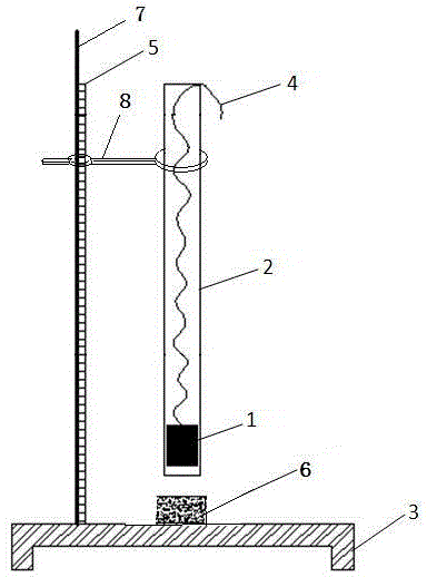
[0016] like figure 1 As shown, an on-site rapid detection device for the freezing strength of backfill soil in permafrost regions is mainly composed of a drop hammer 1, a guide groove 2, a backing plate 3, a traction line 4 and a scale 5, and the backing plate 3 is a thick steel plate, which can withstand repeated It is not easy to deform due to impact; the guide groove 2 is a smooth PE, or PVC pipe, or stainless steel pipe; the pulling wire 4 is a strong and soft thin wire. The drop hammer 1 is placed at the bottom of the guide groove 2, the traction line 4 connected with the drop hammer 1 is placed outside the guide groove 2, the scale 5 and the bracket 7 are fixed on the backing plate 3, and the bracket 7 has a fixing clip 8, and the fixing clip 8 clips Hold the guide groove 2, place the sample 6 on the backing plate 3, and the sample 6 is opposite to the guide gr...


PUM

PropertyMeasurementUnit
Cross-sectional areaaaaaaaaaaa
Thicknessaaaaaaaaaa

Abstract

The invention discloses a freezing strength on-site fast detection device for backfill soil in a frozen soil area. The device comprises a falling hammer, a guiding groove, a cushion plate, a traction line and a scaleplate. The falling hammer is lifted to a certain height through the traction line. The falling hammer makes free-fall motion along the guiding groove. Frozen soil samples placed on the cushion plate is hammered, and the freezing strength of frozen soil is judged according to the hammer falling time number generated when the samples crack. The device is used for fast judging the freezing strength of the backfill soil, easy and fast to use and easy to operate.

Description

technical field [0001] The invention relates to an on-site rapid detection device for the freezing strength of backfill soil in a frozen soil region, belonging to the field of geotechnical property testing instruments for frozen soil. Background technique [0002] In the foundation construction process of projects in cold regions, open cut foundations are mostly used. According to the construction technology, the foundation is first excavated by large-scale machinery, and the foundation is formed and concrete poured in the excavated foundation pit, or the foundation is assembled. After the foundation is completed, the excavated soil is backfilled, thus Complete the construction of the entire foundation. As a result, a large amount of backfill soil was formed around the foundation. [0003] As a kind of artificial filling, the backfill is disturbed soil. In the initial stage after the completion of the project construction, it is a stage of drastic change of the backfill. ...

Claims


Application Information

Patent Timeline
IPC IPC(8): G01N3/34
Inventor 俞祁浩张海宁王俊峰郭磊马丽山谢艳丽
Owner COLD & ARID REGIONS ENVIRONMENTAL & ENG RES INST CHINESE
Learn More