
Fuzz button inter-board electric connector

An electrical connector and wool button technology, applied in the field of electrical connectors between wool button boards, can solve the problems of increased gap between printed boards, difficult disassembly, inconvenient use, etc., and achieves zero insertion force, small size, contact Reliable effect

Pending Publication Date: 2015-10-28
吕永锋
View PDF6 Cites 16 Cited by
  • Summary
  • Abstract
  • Description
  • Claims
  • Application Information

AI Technical Summary

Problems solved by technology

[0004] The traditional board-to-board electrical connector has the following defects: 1. The traditional board-to-board electrical connector needs to be paired with male and female connectors, and the height after mating is relatively high, which increases the gap between printed boards; 2. Traditional board-to-board electrical connectors have high positioning requirements, and it is difficult to align and insert when used in multiple groups; 3. Traditional board-to-board electrical connectors have a certain insertion force when male and female are mated, and plugging and unplugging when using multiple groups The force is very large, which makes it difficult to install and disassemble the printed board and is easily damaged by force; 4. The traditional inter-board electrical connector is large in size, which increases the volume and weight of electronic equipment; 5. The traditional inter-board electrical connection The device is only suitable for passing low-frequency signals and low-speed transmission
These shortcomings have caused great inconvenience and limitations in the use of traditional board-to-board electrical connectors, and have gradually become an urgent issue in the industry.

Method used


Image

  • Fuzz button inter-board electric connector
  • Fuzz button inter-board electric connector
  • Fuzz button inter-board electric connector

Examples


Embodiment Construction

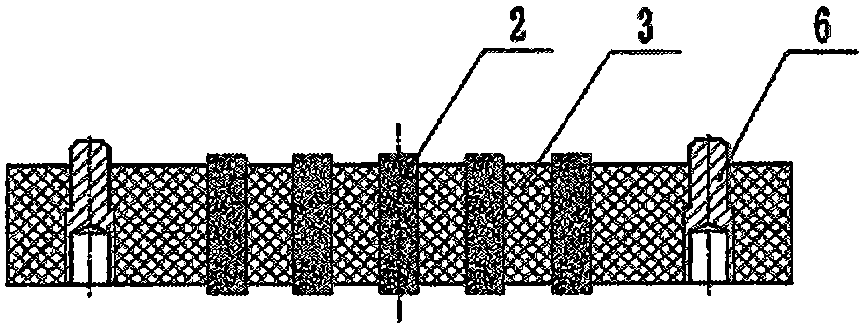
[0021] figure 1 It is a structural schematic diagram of an electrical connector between fur button boards. A group of messy wire pins 2 and accessories 6 are installed in the holes on the insulating mounting plate 3, and the two ends of the messy wire pins 2 are exposed on the insulating mounting plate 3. outside. The messy wire pin 2 is used as a contact piece, and the accessory 6 plays the role of guiding, locating and fixing the insulating mounting plate 3 .

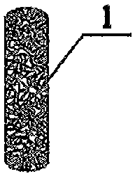
[0022] figure 2 is a schematic diagram of the structure of the random wire pin, and the random wire pin 2 is a cylindrical pin formed by randomly winding the metal wire 1 .

[0023] image 3 It is a schematic diagram before the vertical connection between the printed board and the printed board is realized by using the button-to-board electrical connector. Figure 4 It is a schematic diagram after the vertical connection between the printed board and the printed board is realized by using the button-to-board elec...


PUM


Abstract

According to the invention, random wire pins are used as contacts. A group of random wire pin and accessories are arranged on an insulation mounting plate to form a fuzz button inter-board electric connector. The fuzz button inter-board electric connector is in face contact with printed circuit boards. The insertion force is zero. The fuzz button inter-board connector is arranged between upper and lower printed circuit boards, and the printed circuit boards are vertically connected. By superimposing metal pins, pads of the printed circuit boards and wires are in connection without solder pressure and insertion force. The application range of the fuzz button inter-board electric connector is extended. The fuzz button inter-board electric connector can realize a variety of flexible and reliable interconnection solutions, can be used to connect almost all metal surfaces and metal surfaces and wires, can realize flat and compact internal interconnection of the printed circuit boards, can meet extreme environmental conditions of high reliability, high-speed signal, small space and high density, and is an ideal interconnection solution.

Description

Technical field [0001] The invention belongs to the field of electrical connectors, in particular to an electrical connector between fur button boards. Background technique [0002] In electronic equipment, there are often multiple printed boards, and some printed boards are vertically stacked and installed. However, the interconnection and intercommunication of signals cannot be avoided between printed boards installed in vertical stacks. At this time, inter-board electrical connectors are often required. [0003] The traditional inter-board electrical connectors are used in pairs with male connectors and female connectors. The male connector and the female connector are respectively preset on the two printed boards that need to be connected vertically, and then mated after alignment to complete the vertical connection between the boards. [0004] The traditional board-to-board electrical connector has the following defects: 1. The traditional board-to-board electrical co...

Claims


Application Information

Patent Timeline
IPC IPC(8): H01R12/70H01R13/02H01R13/639H01R13/629
CPCH01R12/70H01R13/02H01R13/629H01R13/646
Inventor 吕永锋
Owner 吕永锋
Learn More