Method and apparatus for scoring the reliability of shock advisory during cardiopulmonary resuscitation
A cardiopulmonary resuscitation, reliability technology, applied in the direction of electrotherapy, application, cardiac defibrillator, etc., can solve the problems of potential rhythm error determination, wrong call, imperfection, etc., and achieve the effect of improving quality
- Summary
- Abstract
- Description
- Claims
- Application Information
AI Technical Summary
Problems solved by technology
Method used
Image

Examples
Embodiment Construction
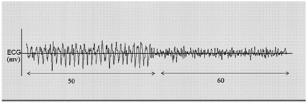
[0033] With further reference to the accompanying drawings, figure 2 An exemplary 23 second ECG strip from a subject patient whose underlying cardiac rhythm is VF is illustrated. The first half of the waveform (left hand side 50) is recorded during CPR and the second half (right hand side 60) is recorded after CRP has been paused (eg, no chest compression artifacts on the ECG data). It can be seen that chest compression artifacts induced on the left hand side 50, ECG during CPR mask the underlying VF rhythm. Previously known shock advice algorithms when applied to the left hand side 50 may evaluate CPR artifacts as a regular ECG rhythm and incorrectly determine to advise no shock. This is the opposite of the evaluation of the right-hand 60 waveform without CPR artifacts. In the right hand, the shock recommendation algorithm was able to accurately detect the VF rhythm and recommend a shock appropriately. therefore, figure 2 The problem of obtaining accurate ECG readings d...
PUM
 Abstract
Description
Claims
Application Information
 - R&D
- Intellectual Property
- Life Sciences
- Materials
- Tech Scout
- Unparalleled Data Quality
- Higher Quality Content
- 60% Fewer Hallucinations
Browse by: Latest US Patents, China's latest patents, Technical Efficacy Thesaurus, Application Domain, Technology Topic, Popular Technical Reports.
© 2025 PatSnap. All rights reserved.Legal|Privacy policy|Modern Slavery Act Transparency Statement|Sitemap|About US| Contact US: help@patsnap.com