Device for controlling vehicle drive devices

A control device and wheel technology, applied in the direction of transmission control, control device, power device, etc., to achieve the effect of reducing idling

Active Publication Date: 2015-10-28
AISIN AW CO LTD
View PDF7 Cites 4 Cited by
  • Summary
  • Abstract
  • Description
  • Claims
  • Application Information

AI Technical Summary

Problems solved by technology

However, since there is a time lag from the engagement command flag of the output clutch to the actual generation of the clutch engagement force, there is a possibility that engine rotation may slip or engine torque transmission may be delayed due to such a time lag.

Method used


Image

  • Device for controlling vehicle drive devices
  • Device for controlling vehicle drive devices
  • Device for controlling vehicle drive devices

Examples


Embodiment Construction

[0017] Hereinafter, each embodiment will be described in detail with reference to the drawings.

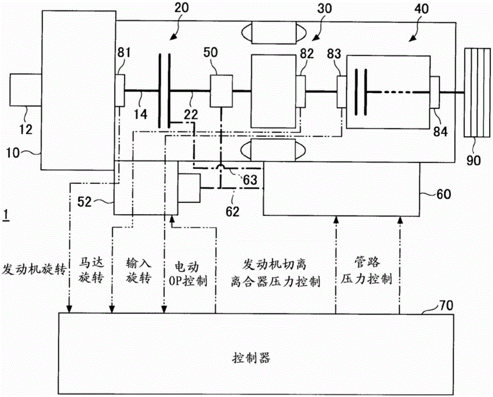
[0018] figure 1 It is a diagram showing an example of a vehicle drive system including an embodiment of the vehicle drive device 1 . It should be stated that in figure 1 In , the single-dot-dash line represents the hydraulic pipeline, and the double-dot-dash line represents the transmission line of the electrical signal. It should be noted that connections via transmission lines for electrical signals need not be figure 1 The direct connection as shown may be a connection via another control device or a bus such as CAN (controller area network).

[0019] The vehicle drive device 1 includes an input shaft 22 , an engine disconnect clutch 20 , an electric motor 30 , and a controller 70 .

[0020] The input shaft 22 is connected to the output shaft 14 of the engine 10 . Engine 10 is started by starter 12 . An engine speed sensor 81 for detecting the engine speed is provided on ...


PUM


Abstract

According to the present invention, vehicle drive devices (1, 2) have: an output shaft (14) connected to an engine (10) started up by a starter (12); an input shaft (22) connected to a vehicle wheel (90); an electric motor (30) for generating rotational torque of the vehicle wheel (90); and a hydraulic clutch (20) for connecting the input shaft (22) and the output shaft (14) when in an engaged state and disconnecting the output shaft (14) from the input shaft (22) when in a disengaged state. The hydraulic clutch (20) is a normally open type of clutch that forms the engaged state by being supplied with oil. A device (70) for controlling the vehicle drive devices (1, 2) begins to supply oil to the hydraulic clutch (20) before the rotating speed of the engine (10) reaches the rotating speed of the input shaft (22) when the startup of the engine (10) is initiated by the starter (12) while the hydraulic clutch (20) is in the disengaged state and the engine (10) has stopped, and while either the input shaft (22) is being rotated by the electric motor (30) or the input shaft (22) is being rotated by inertia travel.

Description

technical field [0001] The present disclosure relates to a control device of a vehicle drive device. Background technique [0002] A control device for a hybrid vehicle is known. The hybrid vehicle includes an engine and a motor as power sources, a transmission connected to the motor, a clutch inserted between the engine and the motor or between the engine and the transmission, and a clutch connected to the transmission. Drive wheels, the above-mentioned hybrid vehicle switches the engine and the motor or drives the vehicle through both the engine and the motor, and the control device of the hybrid vehicle is equipped with: a generator connected to the output shaft of the engine; and a control unit in the When switching power from the motor to the engine, the engine is started using a generator connected to the output shaft of the engine as a starter motor, and the clutch is engaged when the rotation speeds of the motor and the engine match (for example, refer to Patent Docu...

Claims


Application Information

Patent Timeline
Patent Type & Authority Applications(China)
IPC IPC(8): B60W10/02B60K6/387B60K6/48B60K6/543B60K6/547B60L11/14B60W20/00F16D48/02F16H61/02B60L50/16
CPCB60K6/387B60K6/48B60K6/543B60K6/547B60L1/003B60L11/14B60L15/2054B60L2240/36B60L2240/421B60L2240/441B60L2240/507B60W10/02B60W10/06B60W10/115B60W20/00B60W20/40F16D48/02F16H61/02Y02T10/642Y02T10/70Y02T10/7077Y02T10/7275B60L50/16B60W10/023B60W10/08B60W20/10B60W2510/0638B60W2510/0283B60W2510/30F16D2048/0245F16D48/06F16D2500/1066F16D2500/30426F16D2500/3067F16D2500/3166Y02T10/72Y10S903/914Y10S903/93Y10S903/946Y02T10/62Y02T10/64Y02T10/7072B60W10/30B60W2710/021B60W2710/0644B60W2710/081
Inventor 吉田高志津田耕平
Owner AISIN AW CO LTD
Why Eureka
Try Eureka