Work fixture for T-shaped automatic door guide rails

A tooling fixture and automatic door technology, applied in the direction of manufacturing tools, clamping, positioning devices, etc., can solve difficult problems and achieve the effects of precise processing, stable processing, and convenient clamping

Active Publication Date: 2015-11-04
江苏普拉迪数控科技有限公司
View PDF5 Cites 10 Cited by
  • Summary
  • Abstract
  • Description
  • Claims
  • Application Information

AI Technical Summary

Problems solved by technology

But because the section of the automatic door guide rail is T-s

Method used


Image

  • Work fixture for T-shaped automatic door guide rails
  • Work fixture for T-shaped automatic door guide rails
  • Work fixture for T-shaped automatic door guide rails

Examples


Embodiment Construction

[0022] The technical solutions of the present invention will be further described below in conjunction with the accompanying drawings and through specific implementation methods.

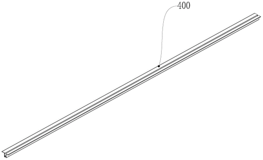
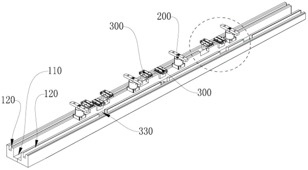
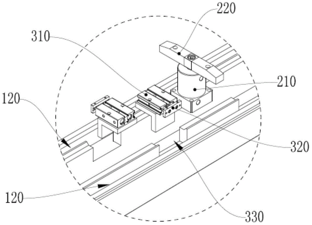
[0023] Such as Figure 1-4 As shown, a tooling fixture for a T-shaped automatic door guide rail includes a mounting base 100, a rotating lower pressing part 200 and a side pressing part 300;

[0024] The upper surface of the installation base 100 is provided with a strip-shaped installation groove 110, and the upper surface of the side wall of the installation groove 110 is provided with a limit groove 120 matching the lower side of the T-shaped automatic door guide rail blank 400; The side wall of the installation groove 110 is provided with a notch, and the notch communicates with the inside of the limiting groove 120;

[0025] The rotating pressing part 200 and the side pressing part 300 are arranged in the installation groove 110; the rotating pressing part 200 presses and fixes the T-shaped au...


PUM


Abstract

The invention relates to the field of machine manufacturing, in particular to a work fixture for T-shaped automatic door guide rails. The work fixture comprises a mounting base, rotary downward-pressing pieces and lateral pressing pieces. The work fixture is provided with limiting grooves matched with T-shaped automatic door guide rail blanks in shape, and the side faces and the upper faces of the limiting grooves are provided with the rotary downward-pressing pieces and the lateral pressing pieces for limiting and fixing respectively. Accordingly,the T-shaped automatic door guide rail blanks can be clamped more conveniently, stably and accurately, and therefore the T-shaped automatic door guide rail blanks are made to be stably and accurately fixed to a workbench of a machine tool, and stable and precise machining is achieved.

Description

technical field [0001] The invention relates to the field of mechanical manufacturing, in particular to a tooling fixture for a T-shaped automatic door guide rail. Background technique [0002] Machinery manufacturing is inseparable from metal cutting machine tools, and machine tool fixtures are one of the indispensable important process equipment to ensure the quality of machining, improve production efficiency, reduce labor intensity, reduce excessive requirements for workers' skills, and realize the automation of production process. Machine tool fixtures are widely used in the manufacturing industry, and the use of a large number of special machine tool fixtures provides the necessary conditions for mass production. [0003] With the rapid development of the processing and manufacturing industry, the precision and production efficiency of the processing parts are required to be higher, which is reflected in the concentration of processes in the processing, and the process...

Claims


Application Information

Patent Timeline
IPC IPC(8): B23Q3/08B24B41/06
CPCB23Q3/069B23Q3/08B23Q2703/04B24B41/06
Inventor 叶永安赵小雨
Owner 江苏普拉迪数控科技有限公司
Why Eureka
Try Eureka