Plane joint manipulator

A technology of planar joints and manipulators, applied in the field of manipulators, can solve the problems of small transmission distance and low product output rate, and achieve the effect of improving the efficiency of film transfer and improving the flexibility of use

Active Publication Date: 2017-03-15
SUZHOU INST OF NANO TECH & NANO BIONICS CHINESE ACEDEMY OF SCI
View PDF8 Cites 0 Cited by
  • Summary
  • Abstract
  • Description
  • Claims
  • Application Information

AI Technical Summary

Problems solved by technology

Although foreign planar joint vacuum manipulators can achieve a vacuum degree of 10 -8 However, there are the following disadvantages: the transmission distance is smaller than the diameter of the cavity; the transmission distance of the linear manipulator can be greater than a radius, but they are all in single-head mode, and only one type of sample can be transmitted, and the product output rate Low

Method used


Image

  • Plane joint manipulator
  • Plane joint manipulator
  • Plane joint manipulator

Examples


Embodiment Construction

[0024] The specific embodiments of the present invention will be described in further detail below with reference to the accompanying drawings and embodiments. The following examples are intended to illustrate the present invention, but not to limit the scope of the present invention.

[0025] The purpose of the present invention is to provide a plane articulated manipulator with large transmission distance and high efficiency in view of the deficiencies of the prior art.

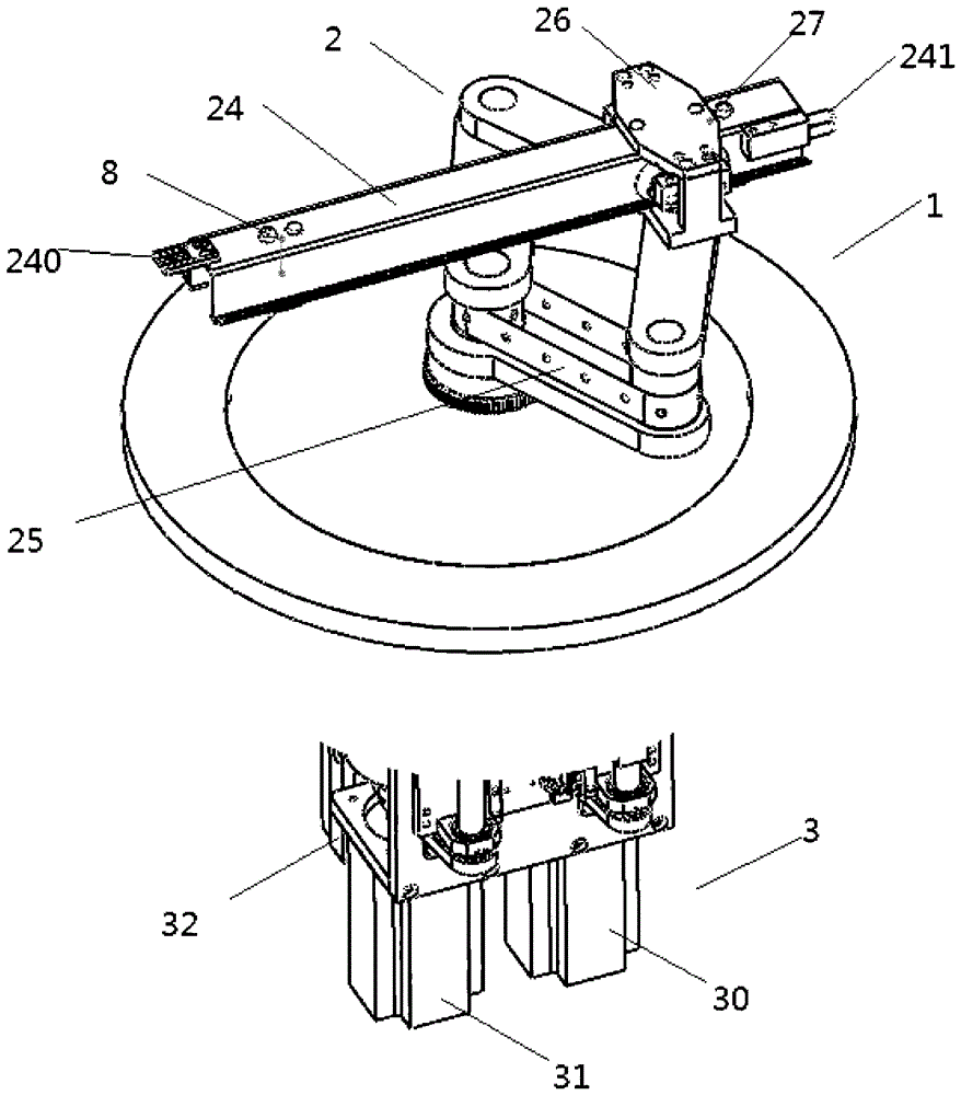
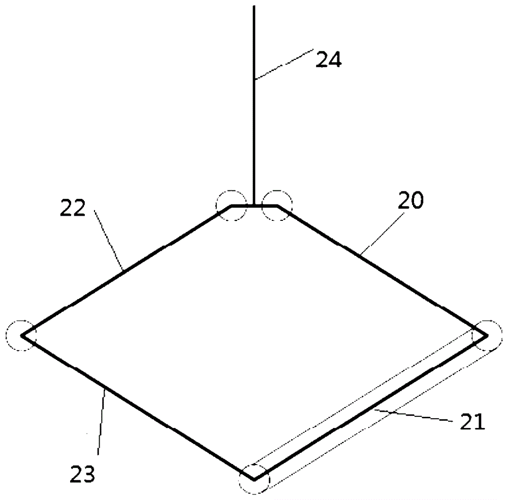
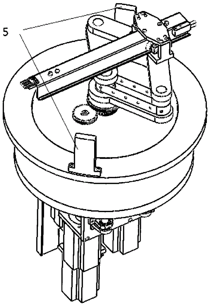
[0026] see Figure 1 to Figure 2 , the plane joint manipulator provided by the embodiment of the present invention includes:

[0027] A vacuum chamber 1 composed of a sealing plate and a vacuum cover, an actuator 2 placed on the sealing plate inside the vacuum chamber 1, and a driving mechanism 3 outside the vacuum chamber 1;

[0028] In the embodiment of the present invention, the sealing plate may use a welded bellows to achieve vacuum sealing, but the bellows is not limited to any device that can achie...


PUM


Abstract

The invention relates to the field of manipulators, in particular to a planar articulated manipulator. It includes: a vacuum chamber composed of a sealing plate and a vacuum cover, an actuator inside the vacuum chamber placed on the sealing plate, and a driving mechanism outside the vacuum chamber; the actuator includes first forearms connected in sequence , the second forearm, the third forearm and the fourth forearm, and also includes an arm connecting base and a telescopic arm with a first clamp installed at one end, the arm connecting base is connected with the first and third forearms, telescopic The arm is fixed on the arm connection base through a spring thimble installed near the outside of the arm connection base; the driving mechanism is used to rotate the telescopic arm in the vacuum cavity by driving the rotation of the second small arm and the fourth small arm , telescopic. The planar articulated manipulator provided by the invention has large transmission distance and high efficiency.

Description

technical field [0001] The invention relates to the field of manipulators, in particular to a plane joint type manipulator. Background technique [0002] A vacuum manipulator is a manipulator that works in a vacuum environment and is mainly used in the semiconductor industry to realize the transfer of wafers in a vacuum chamber. With the development of semiconductor technology, the requirements for vacuum degree of related equipment are getting higher and higher. Because the deposition of thin films under ultra-high vacuum conditions can reduce the residue and influence of residual gases, impurities and defects at the surface and interface are reduced. [0003] According to different transmission modes, vacuum manipulators can be divided into plane joint manipulators and radial linear motion (R-θ) manipulators. Because the plane joint manipulator can achieve multiple degrees of freedom and the movements are more flexible, the plane joint manipulator is widely used. [000...

Claims


Application Information

Patent Timeline
Patent Type & Authority Patents(China)
IPC IPC(8): B25J9/08B25J18/02H01L21/677
Inventor 杨辉张宝顺吴燕华
Owner SUZHOU INST OF NANO TECH & NANO BIONICS CHINESE ACEDEMY OF SCI
Why Eureka
Try Eureka