Stone Chainsaw Cutting Machine

A saw cutting machine and stone chain technology, which is applied in the field of stone chain saw cutting machines, can solve the problems of cutter head damage, chain saw elongation, loosening, etc., and achieve the effect of improving service life

Inactive Publication Date: 2017-10-20
徐柏龄
View PDF1 Cites 0 Cited by
  • Summary
  • Abstract
  • Description
  • Claims
  • Application Information

AI Technical Summary

Problems solved by technology

During the use of the chain saw, the pin and the socket of the inner chain will gradually wear out, resulting in the chain saw being elongated and loose. It is necessary to adjust the engagement between the chain saw and the sprocket
If the two adjacent sprockets are fixed and cannot be adjusted, it is difficult to make the chain saw mesh with the sprocket, and there will be trembling or skipping teeth, which will affect the cutting and cause abnormal damage to the cutter head.

Method used


Image

  • Stone Chainsaw Cutting Machine
  • Stone Chainsaw Cutting Machine
  • Stone Chainsaw Cutting Machine

Examples


Embodiment Construction

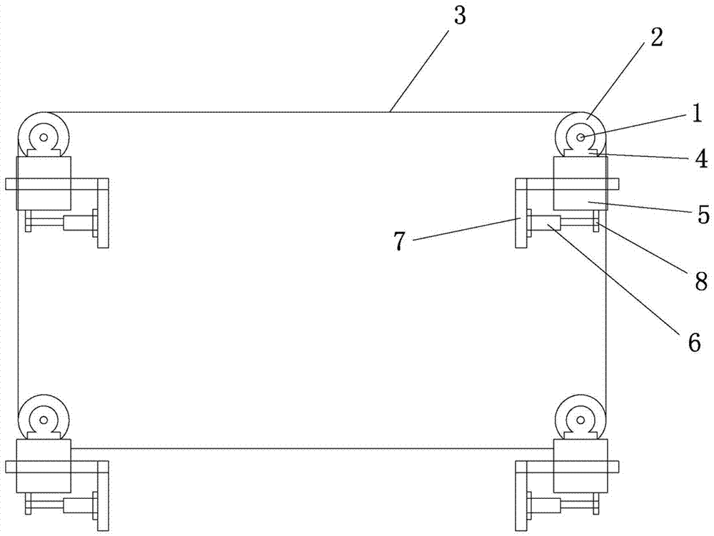
[0018] Stone chain saw cutting machine of the present invention, such as figure 1 As shown, it includes a main shaft, a sprocket, a chain saw, a sliding assembly, and a driving device. The number of the main shaft 1 is four, and each main shaft is provided with a number of sprockets 2, and the chain saw 3 bypasses the sprocket 2. ;Each main shaft 1 is assembled with the bearing and the main shaft box 4, the main shaft box 4 is fixed on the slider 5, the fixed end 6 of the pressure cylinder is connected with the sliding seat 7, and the movable end 8 of the pressure cylinder is connected with the slider 5; The four main shafts 1 are all adjusted to expand and contract through the slide block 5 .

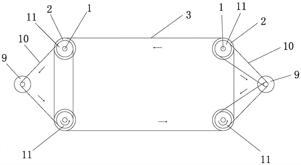
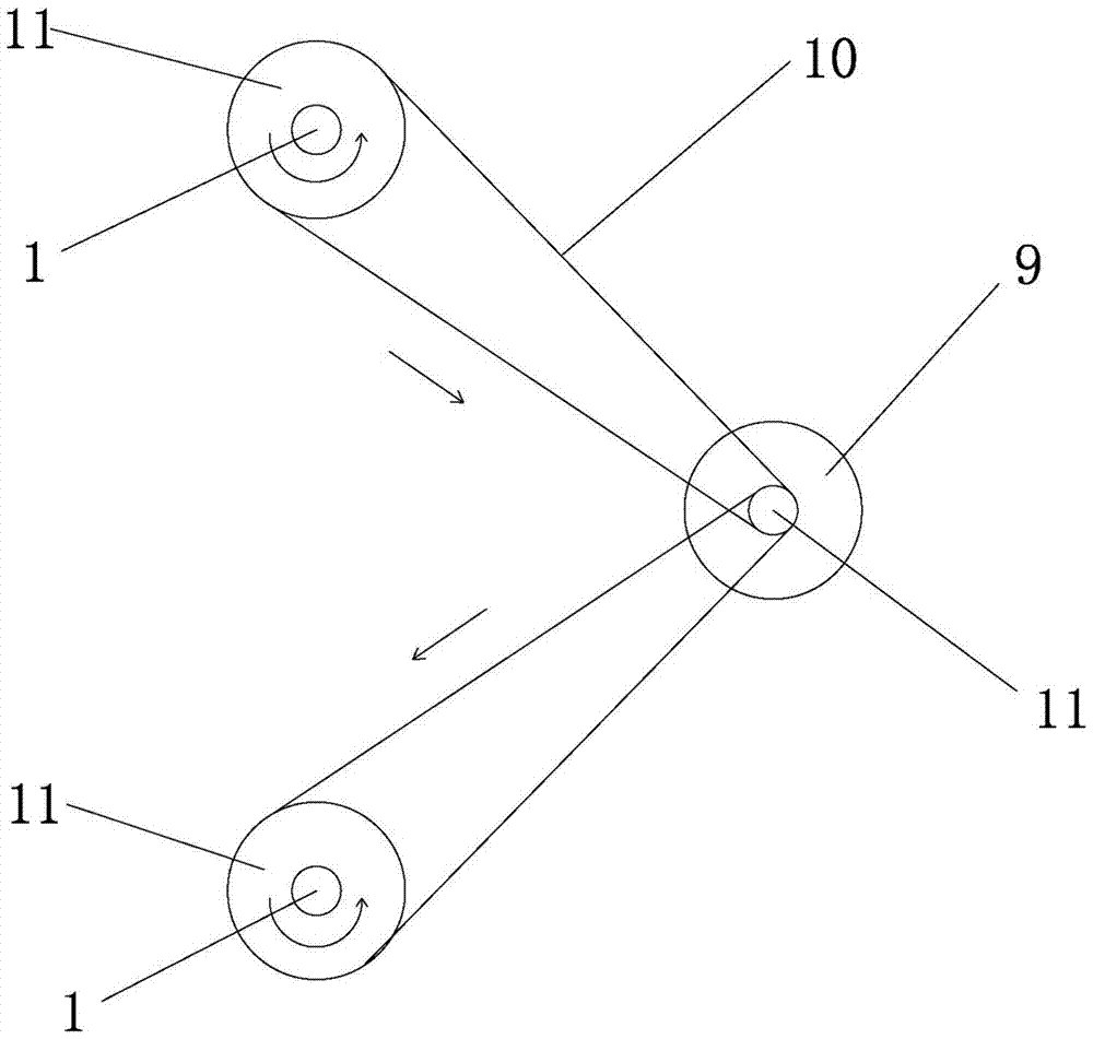
[0019] Another embodiment of the present invention is that the stone chain saw cutting machine includes a main shaft, a sprocket, a chain saw, a sliding assembly, and a driving device. The number of the main shaft 1 is four, and each main shaft is provided with There are several spro...


PUM


Abstract

The stone chain saw cutting machine of the present invention includes a main shaft, a sprocket, a chain saw, a sliding assembly, and a driving device. The number of the main shafts is four, and each main shaft is provided with several sprockets, and the chain saw bypasses the sprockets. ;Each spindle is assembled with the bearing and the spindle box, the spindle box is fixed on the slide block, the fixed end of the pressure cylinder is connected with the slide seat, and the movable end of the pressure cylinder is connected with the slide block; the four spindles are all adjusted by the slide block telescopic. The four main shafts of the driving device of the present invention are all driven synchronously by the motor. There is a servo motor or permanent magnet synchronous motor or stepping motor on both sides of the stone chain saw cutting machine. spindle. The invention can make the chain saw bear relatively equal tension force, make the chain saw run smoothly during cutting, and improve the service life of the chain saw.

Description

technical field [0001] The invention relates to a stone chain saw cutting machine. Background technique [0002] Existing stone material chainsaw cutting machine, only establishes a driving wheel, drives several driven wheels, and its shortcoming is, if Figure 6 As shown, with the 135° center line of the driving sprocket as the boundary, the front section is the pulling force, and the rear section is the pushing force. Because the pushing force and pulling force are not equal, it will cause the chain saw between two adjacent sprockets to pass the sprocket. , a pulling force occurs, making the chain saw tremble, which will affect the service life of the chain saw. The inventor filed an application for a patent for invention on April 8, 2013, with the application number: 201320170806.6, without mentioning the adjustment device of the chain saw. As the chainsaw is in use, the pins and the sockets of the inner chain pieces will gradually wear out, resulting in the chainsaw bei...

Claims


Application Information

Patent Timeline
Patent Type & Authority Patents(China)
IPC IPC(8): B28D1/08B28D7/00
Inventor 徐柏龄
Owner 徐柏龄
Why Eureka
Try Eureka