
Three-channel probe verification method and dedicated verification test block

A calibration method and three-channel technology, applied in the field of automatic ultrasonic flaw detection probe calibration method and calibration test block, can solve the problems of map signal confusion, interface wave width and height, etc. simple and effective effect

Active Publication Date: 2015-11-04
BAOSHAN IRON & STEEL CO LTD
View PDF5 Cites 3 Cited by
  • Summary
  • Abstract
  • Description
  • Claims
  • Application Information

AI Technical Summary

Problems solved by technology

[0003] The technical problem to be solved by the present invention is to provide a three-channel probe calibration method, which uses three calibration holes of different depths to distinguish the channel position, and then simultaneously determines the interface wave occupation width and the bottom wave space margin, eliminating the original automatic Ultrasonic flaw detection probe calibration cannot distinguish whether the channel signal is correct or not, and the boundary wave occupies the width and height, which causes the signal confusion of the map.

Method used


Image

  • Three-channel probe verification method and dedicated verification test block
  • Three-channel probe verification method and dedicated verification test block
  • Three-channel probe verification method and dedicated verification test block

Examples


Embodiment 1

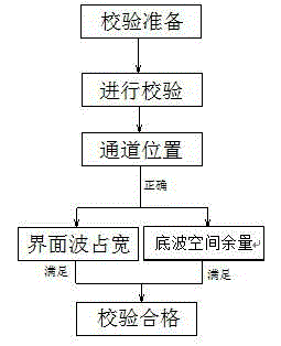
[0024] Such as figure 1 As shown, a three-channel probe calibration method, set the boundary wave occupation width threshold and the bottom wave space margin threshold, and then perform the following steps:

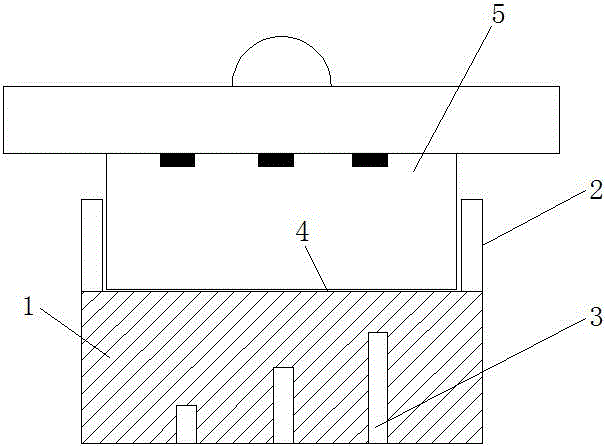
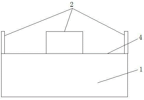
[0025] S1: Set three calibration holes with different depths under the same detection surface, and the three calibration holes correspond to the positions of the three wafers in the probe to be calibrated respectively;

[0026] S2: Start the calibration to obtain the scan chart, and determine the channel position of the probe to be calibrated according to the positions of different defect signals displayed in the three calibration holes on the scan chart. If the channel position is wrong, it is judged that the probe to be calibrated is unqualified, and the process is completed. This verification; if the channel position is correct, continue to the next step;

[0027] S3. When the waveform detected by the probe is stable, determine the width of the interface wave and the ...


PUM


Abstract

The invention relates to the field of ultrasonic flaw detection equipment, in particular to an automatic ultrasonic flaw detection probe verification method and a verification test block. A three-channel probe verification method comprises the steps of setting three verification holes which are different in depth in the same detection surface, judging positions of channels of a to-be-verified probe according to positions of different defect signals displayed by the three verification holes on a scanning image, judging interface wave width and bottom wave margin on the scanning image, determining the to-be-verified probe which meets the condition 1 and the condition 2 at the same time to be qualified, and determining the to-be-verified probe which does not meet the condition 1 and the condition 2 at the same time to be unqualified. The verification test block comprises a verification block body, wherein the top surface of the verification block body is a test block detection surface; the periphery of the top part of the verification block body is provided with a probe positioning fence; the three verification holes are formed in the bottom surface of the verification block body. According to the three-channel probe verification method and the dedicated verification test block, disclosed by the invention, the defects that whether channel signals are accurate or not cannot be distinguished through the verification of an existing automatic ultrasonic flaw detection probe, and the confusion of atlas signals is caused by high interface wave width are removed, accurate positioning of the channel signals is realized, and the verification process is simple and effective.

Description

technical field [0001] The invention relates to the field of ultrasonic flaw detection equipment, in particular to an automatic ultrasonic flaw detection probe calibration method and a calibration test block. Background technique [0002] The automatic ultrasonic flaw detection equipment AUT of the quality inspection station of the thick plate department of the iron and steel plant uses a 1T / 3R combined three-channel special probe, each probe has 3 channels, to ensure correct defect positioning. Probe performance calibration is completed by a set of automatic calibration equipment provided by the foreign party. However, this kind of verification can only prove whether the primary bottom wave performance of the three channels of the probe can meet the requirements, but cannot distinguish the correctness of the position of the probe channels, nor can it know the occupation width of the interface wave. After the probe is put on the machine, it will cause dislocation breakpoint...

Claims


Application Information

Patent Timeline
IPC IPC(8): G01N29/30
Inventor 章谷喻峻沈大良丁振伟
Owner BAOSHAN IRON & STEEL CO LTD
Features
  • Generate Ideas
  • Intellectual Property
  • Life Sciences
  • Materials
  • Tech Scout
  • Unparalleled Data Quality
  • Higher Quality Content
  • 60% Fewer Hallucinations
Learn More