Radar device and control method

A technology of radar devices and controllers, which is applied in the direction of radio wave measurement systems and instruments, and can solve problems such as mutual interference of radar device signals

Active Publication Date: 2015-11-04
李广柱
View PDF6 Cites 12 Cited by
  • Summary
  • Abstract
  • Description
  • Claims
  • Application Information

AI Technical Summary

Problems solved by technology

[0003] One of the objectives of the present invention is to provide a radar device and a control method to solve the technical problem of mutual interference of radar device signals in the same area

Method used


Image

  • Radar device and control method
  • Radar device and control method
  • Radar device and control method

Examples


Embodiment 1

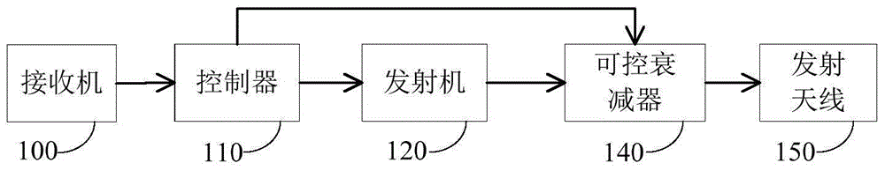
[0026] An embodiment of the present invention provides a radar device, such as figure 1 As shown, it includes a controller 110, a transmitter 120, a transmitting antenna 150 and a receiver 100, and also includes a controllable attenuator 140, the first signal input end of the controllable attenuator 140 is connected to the signal output end of the transmitter 120; The second signal input end of the controllable attenuator 140 is connected with the second signal output end of the controller 110; the signal output end of the controllable attenuator 140 is connected with the signal input end of the transmitting antenna 150; the signal output end of the receiver 100 is connected with the control The signal input terminal of device 110 is connected;

[0027] The transmitter 120 generates a detection signal according to the control signal of the controller 110 and transmits it to the controllable attenuator 140; the controllable attenuator 140 adjusts the transmission power of the d...

Embodiment 2

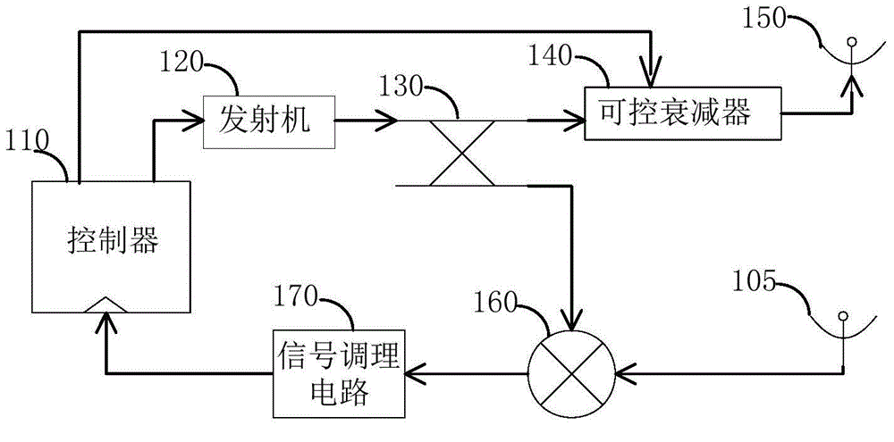
[0031] The embodiment of the present invention also provides a radar device, such as figure 2 As shown, it includes a controller 110, a transmitter 120, a transmitting antenna 150, a receiving antenna 105, a controllable attenuator 140, a coupler 130 and a mixer 160;

[0032] The signal input end of coupler 160 is connected with the signal output end of transmitter 120, and the signal output end of coupler 130 is connected with the first signal input end of controllable attenuator 140; Coupler 130 is used for the detection that transmitter 120 outputs The signal is coupled to the mixer 160;

[0033] The second input end of the mixer 160 is connected with the signal output end of the receiving antenna 105, and the signal output end of the mixer 160 is connected with the signal input end of the signal conditioning circuit 170; The echo signal is mixed with the detection signal to obtain a baseband echo signal.

[0034] Figure 4 It shows a schematic diagram of the working se...

Embodiment 3

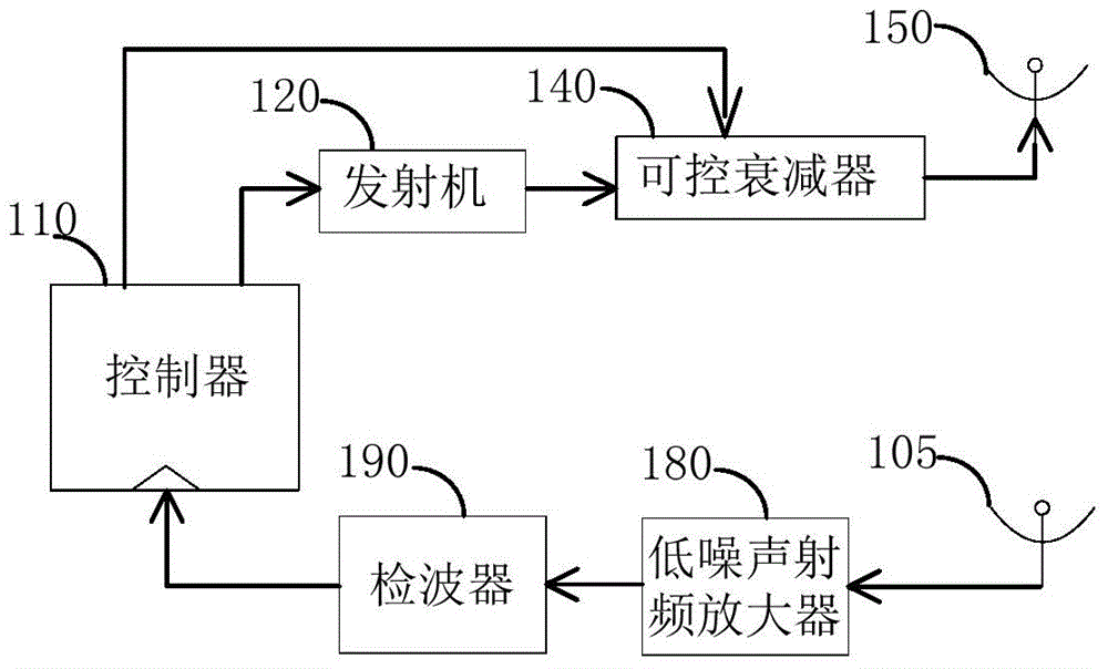
[0047] The embodiment of the present invention also provides a radar device, such as image 3 As shown, it includes a controller 110 , a transmitter 120 , a transmitting antenna 150 , a receiving antenna 105 , a low noise radio frequency amplifier 180 and a detector 190 .

[0048] In the embodiment of the present invention, the controller 110 sends a control signal to the transmitter. The transmitter 120 generates a detection signal according to the control signal and transmits it to the controllable attenuator 140 . The detection signal works in a set frequency band and modulation mode, and adjusting the control signal of the controller 110 can change the frequency band and modulation mode of the detection signal.

[0049] The controller 110 generates a control signal for controlling the controllable attenuator 140, wherein, as Figure 4 As shown, the control signal includes a high level with a duration of CPI or a low level with a duration of CPI. When the control signal ...


PUM


Abstract

The invention relates to a radar device and a control method. The device comprises a controller, a transmitter, a transmitting antenna and a receiver; the device further comprises a controllable attenuator, and a first signal input end of the controllable attenuator is connected with a signal output end of the transmitter; a second signal input end of the controllable attenuator is connected with a second signal output end of the controller; a signal output end of the controllable attenuator is connected with a signal input end of the transmitting antenna; a signal output end of the receiver is connected with a signal input end of the controller; the transmitter generates a detecting signal, and the detecting signal is transmitted to the controllable attenuator; the controllable attenuator adjusts power of the detecting signal sent to the transmitting antenna according to a control signal of the controller; and the controller determines an interference signal according to an echo signal received by the receiver, and adjusts the detecting signal of the transmitter according to the interference signal. Mutual interferences between radar devices in the same area can be prevented, and detection performance is improved.

Description

technical field [0001] The invention relates to the technical field of radar detection, in particular to a radar device and a control method. Background technique [0002] Compared with other active sensors, radar has the advantages of all-weather and long detection distance, so it is widely used in the field of active detection. The density of radars in an area is getting higher and higher. When the frequency bands or modulation methods of two or more radars are the same or similar, the two or more radars will interfere with each other, which will cause the following problems: On the one hand, if Too much interference will increase the burden on the signal processor of the radar, and in extreme cases, the radar will not work; on the other hand, radar interference will obscure the target, affect the detection performance of the radar, and may even misdetect or miss the target . Contents of the invention [0003] One of the objectives of the present invention is to provid...

Claims


Application Information

Patent Timeline
Patent Type & Authority Applications(China)
IPC IPC(8): G01S7/02
CPCG01S7/023
Inventor 李广柱
Owner 李广柱
Why Eureka
Try Eureka