
Experimental heating device

A heating device and experimental technology, which is applied in the direction of laboratory appliances, heating element materials, heating or cooling equipment, etc., can solve the problems of affecting the normal operation of the scanning electron microscope and poor heat insulation effect of the heating table, and achieves simple structure and low manufacturing cost , small size effect

Active Publication Date: 2017-02-22
浙江祺跃科技有限公司
View PDF5 Cites 4 Cited by
  • Summary
  • Abstract
  • Description
  • Claims
  • Application Information

AI Technical Summary

Problems solved by technology

[0002] Scanning electron microscopy is one of the main tools and means for the observation and research of material microstructure. For materials such as superalloys used in high-temperature environments, we need to study their microstructure at high The evolution process of the microstructure during the creep process has led to the rapid development of the heating table accessories of the scanning electron microscope, such as the heating table accessories of the Hitachi company, the heating table accessories of the FEI company, etc., but the heat insulation effect of these commercialized heating tables Poor, which puts the scanning electron microscope around the heating device in a strong thermal field, which seriously affects the normal operation of the scanning electron microscope

Method used


Image

  • Experimental heating device
  • Experimental heating device
  • Experimental heating device

Examples


Embodiment Construction

[0020] The following will clearly and completely describe the technical solutions in the embodiments of the present invention with reference to the accompanying drawings in the embodiments of the present invention. Obviously, the described embodiments are only some, not all, embodiments of the present invention. Based on the embodiments of the present invention, all other embodiments obtained by persons of ordinary skill in the art without making creative efforts belong to the protection scope of the present invention.

[0021] The object of the present invention is to provide an experimental heating device, in particular to an experimental heating device applied in a scanning electron microscope.

[0022] In order to make the above objects, features and advantages of the present invention more comprehensible, the present invention will be further described in detail below in conjunction with the accompanying drawings and specific embodiments.

[0023] Such as figure 2 As sh...


PUM


Abstract

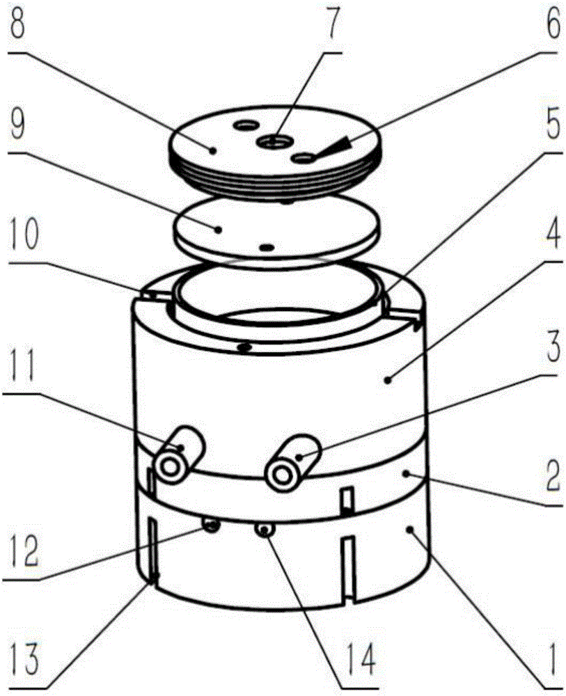
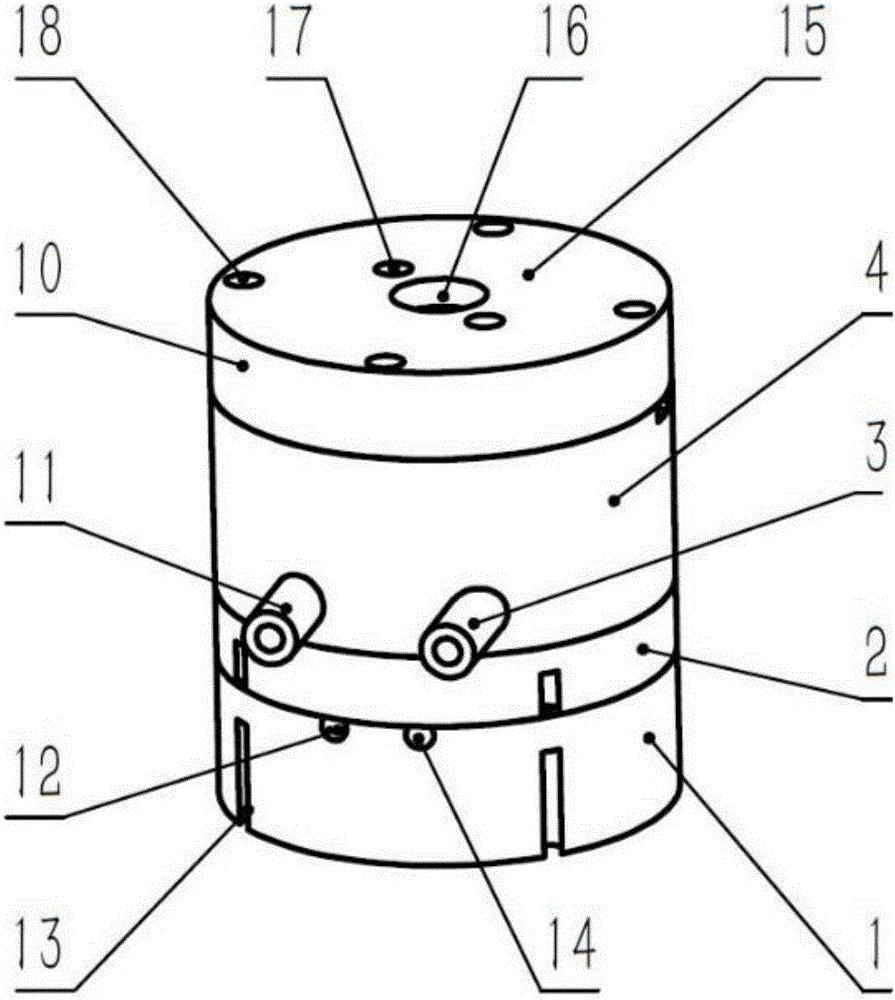
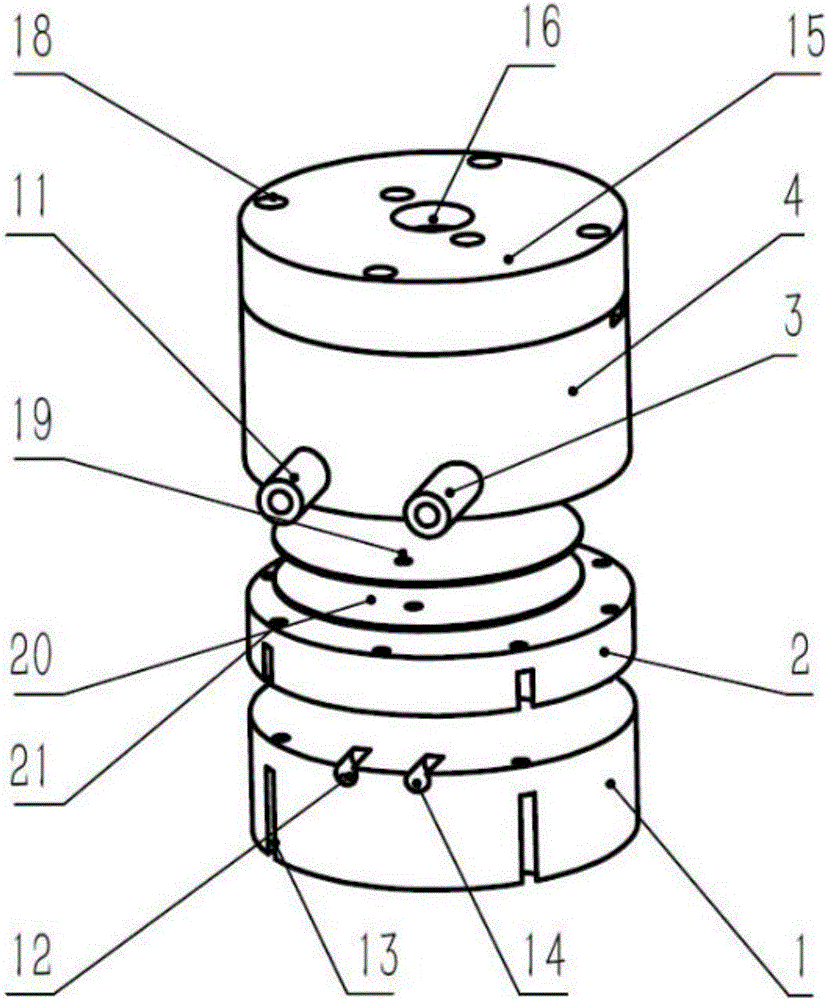
The invention discloses an experimental heating device. The experimental heating device comprises a base, a water cooling base, a heating piece, a first shielding layer, a second shielding layer and an upper cover. The water cooling base is arranged on the base, and the upper cover is arranged on the water cooling base. A heating piece installing groove is formed in the upper end face of the water cooling base, the heating piece is installed on the heating piece installing groove, and the heating piece is connected with an external power source through a circuit. The first shielding layer is arranged on the lower end face of the upper cover, and a containing space is reserved between the heating piece and the first shielding layer. Observation holes are formed in the middle of the first shielding layer and the middle of the upper cover. A circulating water pipeline is arranged in the water cooling base, and a circulating water inlet and a circulating water outlet are formed in the side wall of the water cooling base. The second shielding layer is arranged between the base and the water cooling base. The water cooling structure is adopted for cooling the device, heat radiation of the device to surroundings is reduced through the shielding layers, heat transfer between the device and the external structure is accelerated through the base, heat gathering is avoided, and therefore the influences of heat transfer on normal work of a scanning electron microscope in the heating process are effectively reduced.

Description

technical field [0001] The invention relates to the technical field of heating devices, in particular to an experimental heating device used in scanning electron microscopes. Background technique [0002] Scanning electron microscopy is one of the main tools and means for the observation and research of material microstructure. For materials such as superalloys used in high-temperature environments, we need to study their microstructure at high The evolution process of the microstructure during the creep process has led to the rapid development of the heating table accessories of the scanning electron microscope, such as the heating table accessories of the Hitachi company, the heating table accessories of the FEI company, etc., but the heat insulation effect of these commercialized heating tables Poor, which puts the scanning electron microscope around the heating device in a strong thermal field, which seriously affects the normal operation of the scanning electron microsc...

Claims


Application Information

Patent Timeline
Patent Type & Authority Applications(China)
IPC IPC(8): B01L7/00H05B3/14
CPCB01L7/00H05B3/14
Inventor 张跃飞王晋马晋遥李吉学张泽
Owner 浙江祺跃科技有限公司
Learn More