Lens moving apparatus

A technology of moving the lens and moving the unit, which is applied in the printing device, focusing device, focusing device, etc., and can solve problems such as skeleton vibration

Active Publication Date: 2015-11-04
LG INNOTEK CO LTD
View PDF8 Cites 26 Cited by
  • Summary
  • Abstract
  • Description
  • Claims
  • Application Information

AI Technical Summary

Problems solved by technology

However, the movement of the skeleton in the direction of the optical axis

Method used


Image

  • Lens moving apparatus
  • Lens moving apparatus
  • Lens moving apparatus

Examples


no. 1 approach

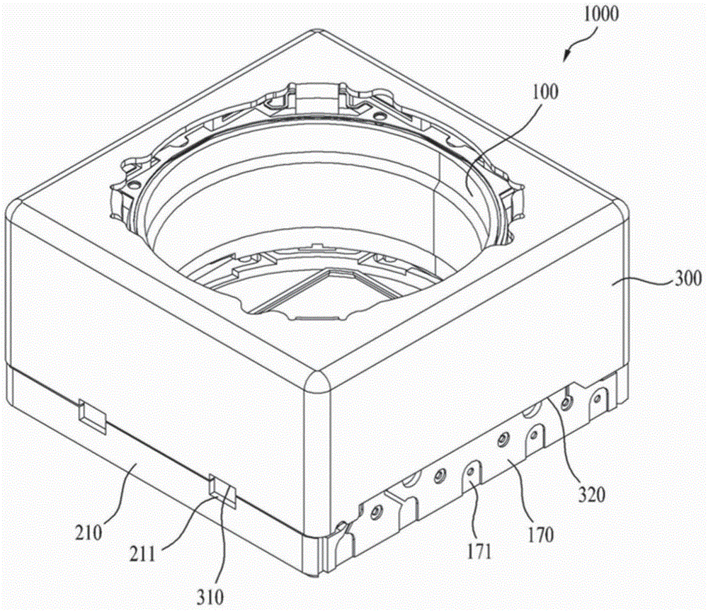
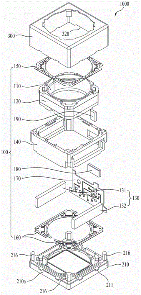
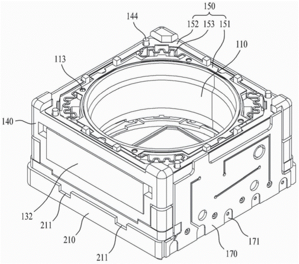
[0053] figure 1 To show a schematic perspective view of the lens shifting device 100 according to the embodiment, figure 2 To show a schematic exploded perspective view of the lens shifting device 100 according to this embodiment, image 3 as shown in the figure 1 A schematic perspective view of the lens shifting device 100 after the cover member 300 is removed, Figure 4 for image 3 schematic floor plan of Figure 5 To show a schematic perspective view of the housing 140 according to this embodiment, Figure 6 as shown from the Figure 5 A schematic perspective view of the casing 140 observed from different angles, Figure 7 To show a schematic bottom perspective view of the housing 140 according to this embodiment, Figure 8 To show a schematic exploded perspective view of the housing 140 according to this embodiment, Figure 9 To show a schematic plan view of the upper elastic member 150 according to this embodiment, and Figure 10 is a schematic plan view showin...

no. 2 approach

[0266] Figure 34 To show an exploded perspective view of a lens shifting device according to another embodiment, Figure 35 To show a perspective view of a lens shifting device without a cover member according to an embodiment, Figure 36 To show a view of the housing and the upper elastic member according to the embodiment, Figure 37 for Figure 36 A side-view cross-sectional view of , and Figure 38 is a view showing graph curves obtained during movement of a conventional lens shifting device and a lens shifting device according to an embodiment.

[0267] refer to Figure 34 to Figure 37 , the lens shifting device according to this embodiment may mainly include a moving unit 100 , a fixing unit 200 , an elastic unit 300 , a damper member 400 and a position sensing unit 500 .

[0268] The moving unit 100 may house a lens or lens unit 10 as described below and is movable. The mobile unit 100 may include a skeleton 110 and a coil unit 120 . The lens unit 10 may be acco...


PUM


Abstract

Embodiments provide a lens moving apparatus including a housing supporting a driving magnet and having an opening, a bobbin provided at an outer circumferential surface thereof with a coil located inside the driving magnet, the bobbin being moved in a first direction parallel to an optical axis within the housing via electromagnetic interaction between the driving magnet and the coil, and a damper located between the housing and the bobbin.

Description

[0001] Cross References to Related Applications [0002] This application claims Korean Patent Application No. 10-2014-0049273 filed in Korea on April 24, 2014, Korean Patent Application No. 10-2014-0055362 filed in Korea on May 9, 2014, and Priority to Korean Patent Application No. 10-2014-0096577 filed in Korea on Jul. 29, 2014, which are hereby incorporated by reference in their entirety as if fully set forth herein. technical field [0003] Embodiments relate to a lens moving device, and more particularly, to a lens moving device that prevents resonance of a frame in the direction of the optical axis by mitigating vibration of the frame in the direction of the optical axis during movement of the lens or performing autofocus. Background technique [0004] In recent years, IT products equipped with mini digital cameras, such as mobile phones, smartphones, tablet computers, and notebook computers, have been actively developed. [0005] An IT product equipped with a convent...

Claims


Application Information

Patent Timeline
IPC IPC(8): G03B5/00G03B13/32
CPCG02B7/09G02B7/08G02B27/646G03B3/10G03B2205/0069
Inventor 李准泽孙秉旭朴相沃李圣民
Owner LG INNOTEK CO LTD
Why Eureka
Try Eureka