Support disc for laminating machine

A technology for supporting discs and laminating machines, which is applied in the direction of manufacturing wire harnesses, etc., can solve problems such as low work efficiency

Inactive Publication Date: 2015-11-04
苏州沃尔非自动化设备有限公司
View PDF8 Cites 0 Cited by
  • Summary
  • Abstract
  • Description
  • Claims
  • Application Information

AI Technical Summary

Problems solved by technology

[0003] At present, in the production and processing of flexible cables, aluminum foil, labels and adhesives are usually required to be laminated. The methods used in the prior art generally complete the lamination work through the lamination process of multiple laminating machines, and one time It can only fit a circle of flexible cables, and the work efficiency is extremely low, and a support plate is needed on the laminating machine to place coils such as flexible cables.

Method used


Image

  • Support disc for laminating machine
  • Support disc for laminating machine

Examples


Embodiment Construction

[0013] Specific embodiments of the present invention will be further described in detail below.

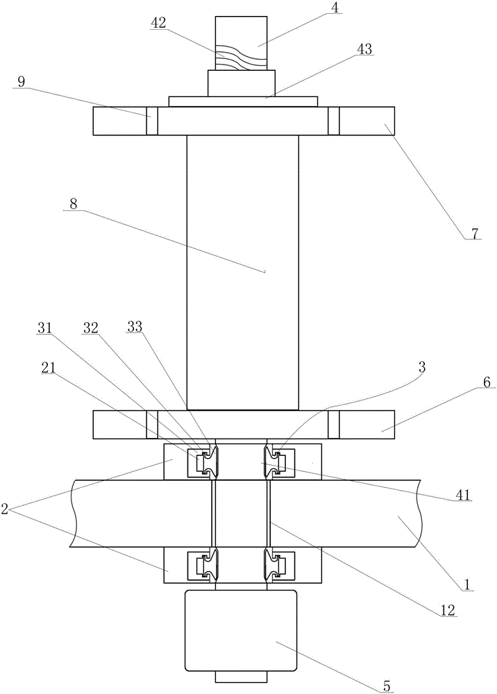
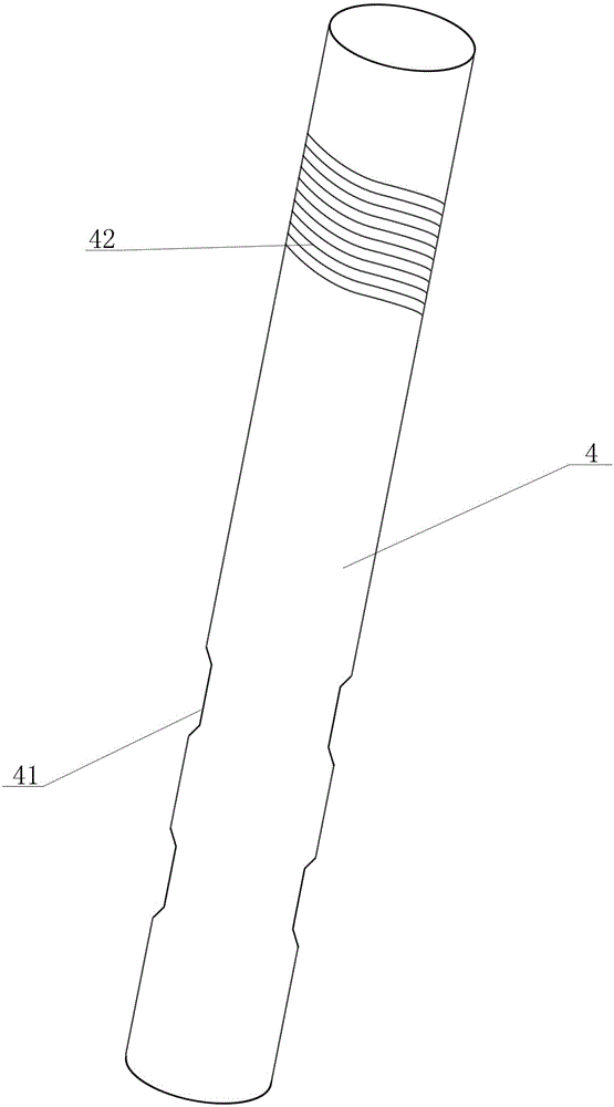
[0014] Such as figure 1 and figure 2 As shown, a support plate for a laminating machine of the present invention includes a frame 1, and is characterized in that: a through hole 12 is provided on the frame 1, and a support block 2 is arranged on the upper and lower sides of the through hole 12, and the support block 2 are provided with a groove 21, a rotating device 3 is arranged in the groove 21, a roller shaft 4 is sleeved on the rotating device 3, a magnetic powder brake 5 is coaxially arranged on the lower part of the roller shaft 4, and the roller shaft 4 is placed on the supporting block The upper part of 2 is connected with lower fixed disk 6, is provided with upper fixed disk 7 on the top of roller shaft 4, also sleeves a cylinder 8 between upper fixed disk 7 and lower fixed disk 6.

[0015] The rotating device 3 includes a "U"-shaped rotating disk 31 arranged in the gr...


PUM


Abstract

The invention provides a support disc for a laminating machine. Support blocks are arranged at the upper end and the lower end of a through hole respectively and used for supporting a roll shaft. A roll shaft is placed in the through hole and shakes. A round of groove is arranged at the inner side of each support block. A rotation device is arranged in the groove and used for convenient and smooth rotation of the roll shaft. A magnetic powder brake is arranged coaxially on the roll shaft and under the support block at the lower part. The magnetic powder brake is used for driving rotation of the roll shaft to drive a wire coil arranged on the roll shaft to rotate. A lower fixed disc is arranged on the roll shaft and above the support block at the upper part and an upper fixed disc is arranged at the upper part of the roll shaft. The lower fixed disc and the upper fixed disc play a supporting role. A cylinder is arranged between the lower fixed disc and the upper fixed disc. The cylinder and the coil match in internal diameter, which facilitates the wire coil to be placed on the cylinder horizontally. The lower fixed disc supports the wire coil. A plurality of wire coils can be placed, which facilitates a laminating machine to carry out simultaneous lamination of the plurality of wire coils during the lamination process, and the working efficiency is raised.

Description

technical field [0001] The invention relates to a supporting device, in particular to a supporting plate for a laminating machine. Background technique [0002] Flexible flat cable is also called Flexible Flat Cable (FFC). The number and spacing of wires can be selected arbitrarily, which makes the connection more convenient, greatly reduces the volume of electronic products, reduces production costs, and improves production efficiency. It is most suitable for moving parts and motherboards. , PCB board to PCB board, used as data transmission cable in miniaturized electrical equipment. At present, it is widely used in the connection between the print head of various printers and the main board, the signal transmission and board connection of plotters, scanners, copiers, audio, LCD appliances, fax machines, various DVD players, etc., in modern electrical equipment. , almost everywhere. [0003] At present, in the production and processing of flexible cables, aluminum foil, l...

Claims


Application Information

Patent Timeline
Patent Type & Authority Applications(China)
IPC IPC(8): H01B13/012
Inventor 殷海涛杨春永尹辉
Owner 苏州沃尔非自动化设备有限公司
Why Eureka
Try Eureka