Design method for microwave cavity band-pass filter

A band-pass filter and design method technology, applied in the microwave field, can solve the problems of insufficient design accuracy, complicated design process, long development cycle, etc., and achieve the effects of clear parameters, reduced development cost, and simple operation

Pending Publication Date: 2015-11-04
NO 54 INST OF CHINA ELECTRONICS SCI & TECH GRP
View PDF4 Cites 10 Cited by
  • Summary
  • Abstract
  • Description
  • Claims
  • Application Information

AI Technical Summary

Problems solved by technology

[0003] However, the network synthesis method to design microwave cavity bandpass filters is only suitable for the design of fixed frequency filters; different filter structures correspond to different design formulas, and the design

Method used


Image

  • Design method for microwave cavity band-pass filter
  • Design method for microwave cavity band-pass filter
  • Design method for microwave cavity band-pass filter

Examples


Embodiment

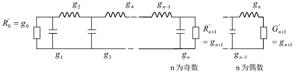
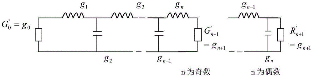
[0028] Embodiment: (a) take the maximum flat type as an example, determine the section number n and the normalized low-pass element value of the filter;

[0029] The design formula for the flattest response:

[0030] L A ( ω ′ ) = 10 log 10 [ 1 + ( 10 L A r / 10 - 1 ) ( ω ′ ω 1 ′ ) 2 ...


PUM


Abstract

The invention discloses a design method for a microwave cavity band-pass filter, relating to the technical field of microwaves. The design method comprises the following steps of: 1, determining cavity numbers n of a filter according to performance index requirement; 2, obtaining a normalized low-pass component value of the filter according to a filter design theory, and calculating an input-output external Q value and inter-cavity coupling bandwidth; 3, respectively building an input-output structural model and an inter-cavity coupling structural model in three-dimensional simulation software high frequency structure simulator (HFSS) according to a selected filter structural form, comparing a simulation result with theoretical data, and obtaining a structural initial value if the difference between the simulation result and the theoretical data is less than a certain order; and 4, building a complete filter model in the three-dimensional simulation software according to the initial value data, and comprehensively optimizing. Through the combined application of the filter design theory and the three-dimensional electromagnetic field simulation software HFSS, the design efficiency and accuracy of the microwave cavity band-pass filter is improved, thus, the development period is shortened, and cost is reduced.

Description

technical field [0001] The invention relates to the field of microwave technology, and is particularly suitable for the design method of a radio frequency front-end cavity fixed or adjustable band-pass filter in a communication system. Background technique [0002] The traditional method for designing microwave cavity bandpass filters is the network synthesis method. The design of microwave band-pass filter by network synthesis method should start from the lumped parameter low-pass filter. After introducing the impedance converter, it can be transformed into a low-pass prototype with only one reactance element, and then according to the frequency conversion, the conversion It is a lumped element bandpass filter. Generally, the impedance converter is regarded as a coupler to form a lumped parameter bandpass filter. Then consider how to realize it with distributed parameters near the passband frequency, so as to complete the design of the whole direct coupled microwave bandpa...

Claims


Application Information

Patent Timeline
IPC IPC(8): H01P11/00
Inventor 王清芬马延爽
Owner NO 54 INST OF CHINA ELECTRONICS SCI & TECH GRP
Why Eureka
Try Eureka