Layout structure and design method of wall-piercing bushing for UHV DC project pole line

A UHV DC, wall bushing technology, used in cable laying equipment, lead-in/pass-through insulators, electrical components, etc., can solve the problem of increased thickness of insulating materials, increased air clearance, and the weight of pole line wall bushings Increase and other problems to achieve the effect of reducing bending moment and avoiding uneven wet flash

Active Publication Date: 2017-05-10
STATE GRID CORP OF CHINA +1
View PDF7 Cites 0 Cited by
  • Summary
  • Abstract
  • Description
  • Claims
  • Application Information

AI Technical Summary

Problems solved by technology

On the one hand, the increase in the external insulation requirements of the pole line leads to an increase in the air clearance between the wall bushing of the pole line and the side wall of the valve hall, which in turn increases the length of the wall bushing of the pole line; on the other hand, the internal insulation requirements of the pole line The improvement of the polar line wall bushing increases the thickness of the insulating material, which in turn leads to an increase in the weight of the polar line wall bushing, and the bending moment of the bushing increases accordingly
However, it is difficult to solve the design and manufacturing problems caused by the large length and bending moment of the wall-piercing bushing for the ±1100kV UHV DC project using the traditional wall-piercing bushing layout structure.

Method used


Image

  • Layout structure and design method of wall-piercing bushing for UHV DC project pole line
  • Layout structure and design method of wall-piercing bushing for UHV DC project pole line
  • Layout structure and design method of wall-piercing bushing for UHV DC project pole line

Examples


Embodiment Construction

[0028] The present invention will be described in detail below in conjunction with the accompanying drawings and embodiments.

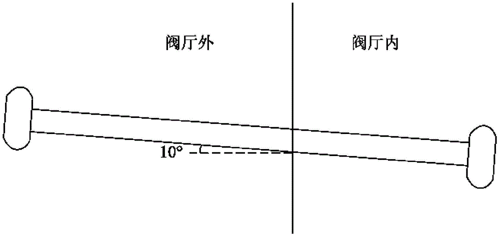
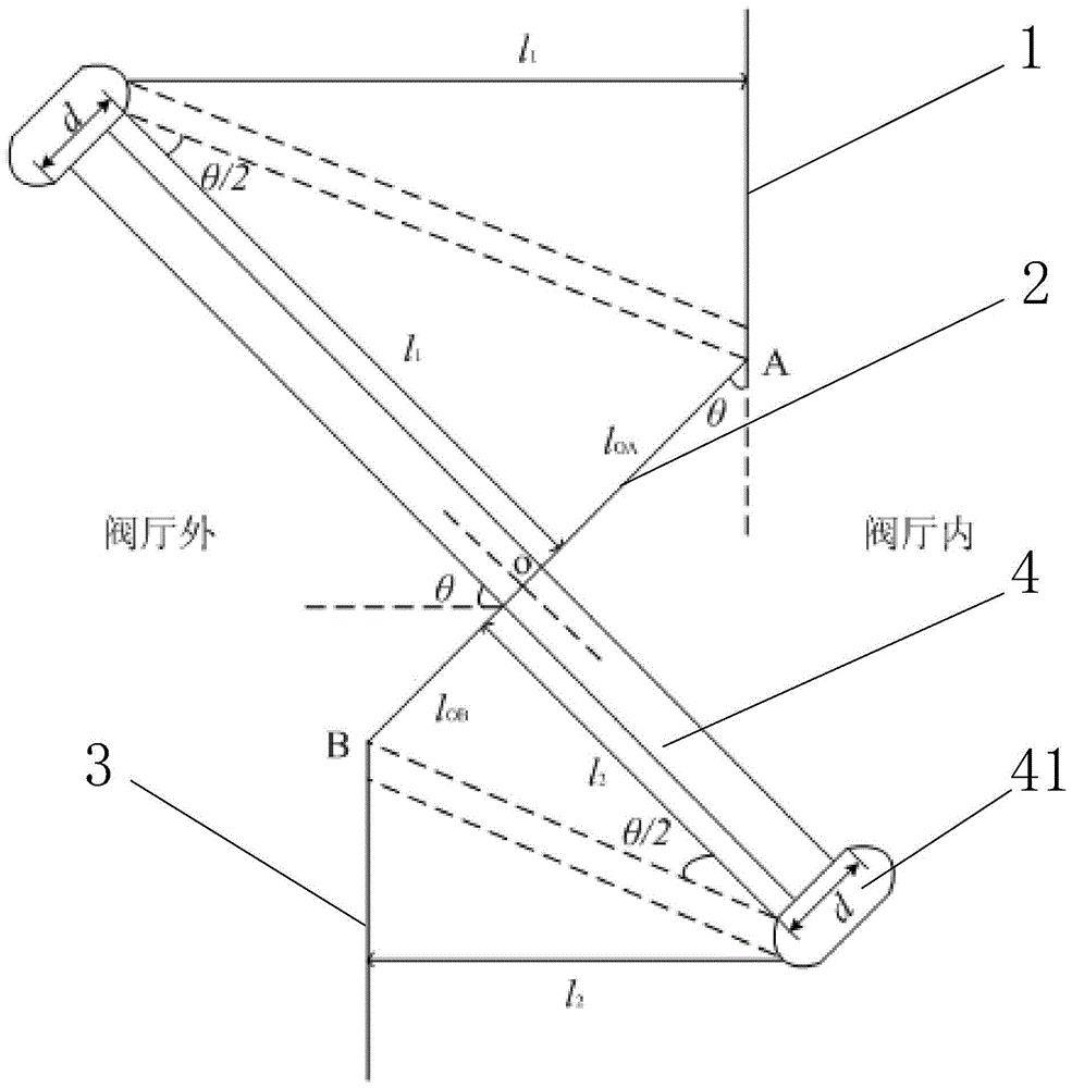
[0029] like figure 2 As shown, the UHV DC project pole line wall bushing layout structure provided by the present invention includes an upper vertical wall 1, and a lower vertical wall staggered by a certain distance from the upper vertical wall 1 in both the horizontal direction and the vertical direction. Wall 3, and the inclined wall 2 connecting the lower end of the upper vertical wall 1 and the upper end of the lower vertical wall 3, the upper vertical wall 1, the inclined wall 2 and the lower vertical wall 3 jointly form the valve hall side wall. The polar line wall-piercing sleeve 4 vertically passes through the inclined wall 2, and the two ends of the polar line wall-piercing sleeve 4 are respectively provided with a pressure equalizing cover 41, and the shortest distance from the pressure equalizing cover 41 outside the valve hall to the upp...


PUM


Abstract

The invention relates to an arrangement structure of a polar line wall bushing of an extra-high-voltage direct-current engineering and a design method thereof. The arrangement structure comprises an upper vertical wall, an inclined wall, a lower vertical wall, and a polar line wall bushing passing through the inclined wall vertically, wherein the walls are successively connected to form a side wall of a valve hall. Grading shields are respectively arranged at the two ends of the polar line wall bushing. A shortest distance between the grading shield, located outside the valve hall, of the polar line wall bushing and the upper vertical wall and the length of the part, located outside the valve hall, of the polar line wall bushing are equal to an air clearance between the grading shield located outside the valve hall and the side wall of the valve hall; and a shortest distance between the grading shield, located inside the valve hall, of the polar line wall bushing and the lower vertical wall and the length of the part, located inside the valve hall, of the polar line wall bushing are equal to an air clearance between the grading shield located inside the valve hall and the side wall of the valve hall. The structure and the method can be widely applied to arrangement of a polar line wall bushing in the extra-high-voltage direct-current engineering; and on the premise that the air clearance requirement is met, the length of the polar line wall bushing is shortest and the bending moment is minimized.

Description

technical field [0001] The invention relates to an arrangement structure and a design method of a wall-piercing bushing for a pole line of a UHV DC project, in particular to an arrangement structure and a design method for a wall-piercing bushing of a ±1100kV UHV DC project pole line. Background technique [0002] As the link connecting the valve hall and the DC field in the DC project, the pole line wall bushing is usually arranged on the side wall of the valve hall. like figure 1 As shown, the traditional wall-piercing bushing layout structure considers two factors: one is to meet the air clearance requirements of the end of the polar line wall-piercing bushing to the side wall of the valve hall; the other is to prevent the polar line wall-piercing The pipe located outside the valve hall caused wet flash due to uneven rain. In the case of comprehensive consideration of the above two requirements, the polar line wall bushing is usually designed to be inclined upward by 10...

Claims


Application Information

Patent Timeline
Patent Type & Authority Patents(China)
IPC IPC(8): H02G3/22H02G1/08
CPCH01B17/26
Inventor 梅念陈东乐波马为民付颖吴方劼于慧芳赵峥
Owner STATE GRID CORP OF CHINA
Why Eureka
Try Eureka