Method for automatically adjusting inclination between image photographing module group sensor and lens

A camera module and automatic adjustment technology, applied in the direction of image communication, TV, electrical components, etc., can solve the problems such as the inability to guarantee the center of the circle and the center of the sensor, low efficiency, long test time, etc.

Active Publication Date: 2015-11-04
NINGBO SUNNY OPOTECH CO LTD
View PDF3 Cites 34 Cited by
  • Summary
  • Abstract
  • Description
  • Claims
  • Application Information

AI Technical Summary

Problems solved by technology

The MTF curve can be used to calculate the inclination between the sensor and the lens when the module is assembled, but the traditional method based on the small-step defocus curve requires a long test time, resulting in low efficiency
[0004] In addition, when the module is assembled, the inclination between th

Method used


Image

  • Method for automatically adjusting inclination between image photographing module group sensor and lens
  • Method for automatically adjusting inclination between image photographing module group sensor and lens
  • Method for automatically adjusting inclination between image photographing module group sensor and lens

Examples


Embodiment Construction

[0037] The following description is used to disclose the present invention so that those skilled in the art can implement the present invention. The preferred embodiments in the following description are only examples, and those skilled in the art can think of other obvious variations. The basic principles of the present invention defined in the following description can be applied to other embodiments, modifications, improvements, equivalents, and other technical solutions that do not depart from the spirit and scope of the present invention.

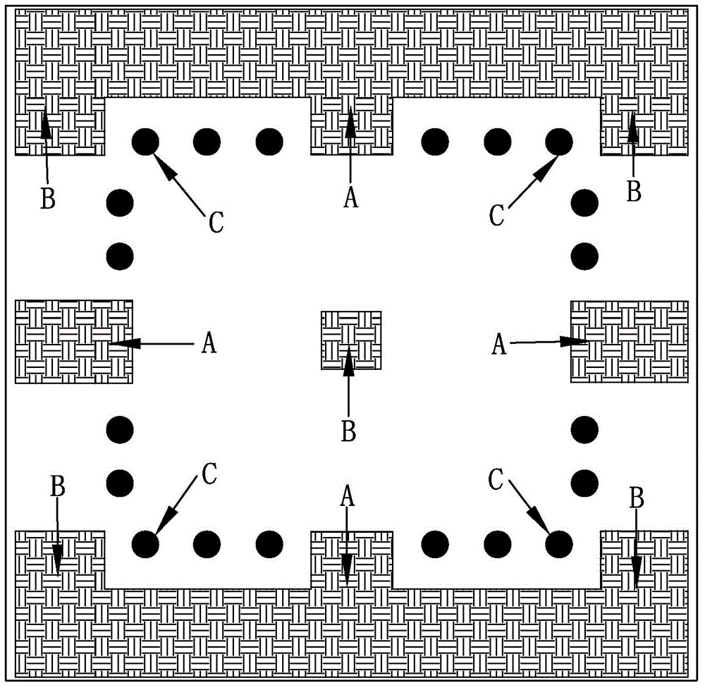
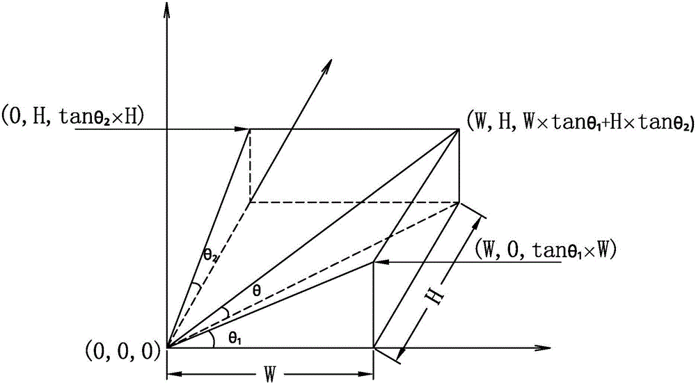
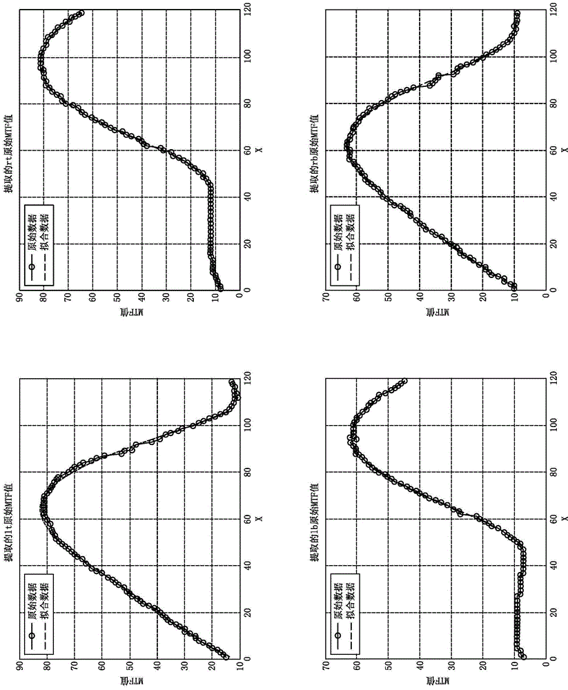
[0038] Such as Figure 1 to Figure 7 Shown is a schematic diagram of a method for automatically adjusting the tilt between the sensor of the camera module and the lens according to a preferred embodiment of the present invention. In the method of the present invention, the test equipment used includes a standard plate, a light source, and a positioning platform, such as a six-degree-of-freedom parallel positioning platform.

[0039] The s...


PUM

PropertyMeasurementUnit
Lengthaaaaaaaaaa
Lengthaaaaaaaaaa

Abstract

The invention provides a method for automatically adjusting inclination between an image photographing module group sensor and a lens. The method comprises the following steps that test light is provided via a light source and a scalar board; a positioning platform drives the lens to move relative to the sensor according to a preset step; an image acquisition system acquires and transmits MTF data of test light of an image photographing module group; curve fitting is performed on the MTF data so that highest point distance difference of the MTF data of a designated area is obtained and thus degree of inclination between the image photographing module group sensor and the lens is calculated; and the image photographing module group is corrected via the positioning platform according to the degree of inclination. Curve fitting is performed on a high-step defocus curve to predict the calculation result of a low-step defocus curve so that efficiency of the whole test is enhanced. Besides, a six-degree-of-freedom parallel positioning platform can be used as the positioning platform so that the center of the positioning platform is ensured to be overlapped with the center of the sensor, and thus inclination between the sensor and the lens is ensured to be corrected accurately and timely.

Description

Technical field [0001] The invention relates to a method for automatically adjusting the tilt (tilt) of a camera module, in particular to a method for calculating the tilt between a sensor and a lens of the camera module based on an image and correcting and adjusting the tilt. Background technique [0002] With the rapid development of the mobile phone industry, high-pixel mobile phone camera modules have very strict requirements for the tilt between the sensor and the lens, and the tilt between the sensor and the lens during module assembly is too high. It will cause unilateral image blur, which directly affects the yield of the product. How to quickly and accurately calculate the tilt and correct it is an important research direction at present. [0003] MTF (Modulation Transfer Function) is an accurate, objective and quantitative image quality evaluation index in the image quality evaluation methods of optical systems. In the same optical system, the original signals with diffe...

Claims


Application Information

Patent Timeline
IPC IPC(8): H04N17/00
Inventor 丁亮张宝忠张扣文王斌
Owner NINGBO SUNNY OPOTECH CO LTD
Why Eureka
Try Eureka