Arrangements for removing entrained catalyst particulates from gas

一种催化剂颗粒、气体的技术,应用在催化剂再生/再活化、物理/化学过程催化剂、催化裂化等方向,能够解决催化剂颗粒阻塞、减小催化剂颗粒催化效果等问题

Inactive Publication Date: 2015-11-11
PALL CORP
View PDF6 Cites 0 Cited by
  • Summary
  • Abstract
  • Description
  • Claims
  • Application Information

AI Technical Summary

Problems solved by technology

Over time, the catalyst particles become clogged with fouling such as coke-like substances, which reduces the catalytic effectiveness of the catalyst particles

Method used


Image

  • Arrangements for removing entrained catalyst particulates from gas
  • Arrangements for removing entrained catalyst particulates from gas

Examples


Embodiment Construction

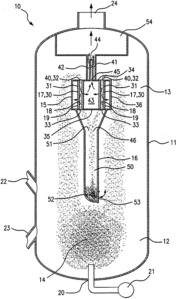
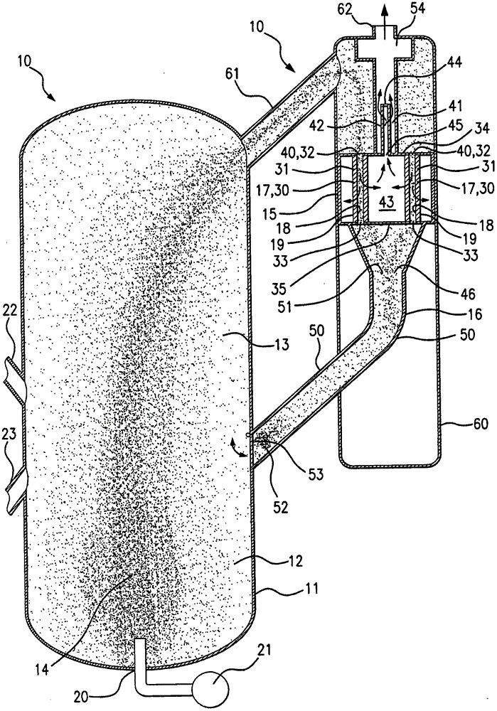
[0008] Many different means for removing entrained catalyst particles from gases (including vapors) may embody the present invention. In one instance of many instances such as figure 1 As shown in , apparatus 10 may include a pressure vessel 11 having a lower region 12 and an upper region 13 . The lower region 12 may be arranged to contain a fluidized bed 14 of catalyst particles suspended in a gas. The upper zone 13 may be arranged to receive gas and entrained catalyst particles from the fluidized bed 14 which are scrubbed or diffused. The device 10 may also include a filter assembly 15 and a sinker leg or tube 16 . The filter assembly 15 includes a permeable filter medium 17 having a feed side 18 and a filtrate side 19 separated from the feed side 18 by means of the filter medium 17 . Dispersed gas and entrained catalyst particles from the fluidized bed 10 may be driven into the filter assembly 15 by pressure inside the pressure vessel or by a blower, fan, compressor (not...


PUM

PropertyMeasurementUnit
heightaaaaaaaaaa

Abstract

An arrangement for removing entrained catalyst particulates from a gas may include a pressure vessel, a filter assembly, and a dip leg. The pressure vessel may contain a fluidized bed of catalyst particulates suspended in the gas. Some of the gas and entrained catalyst particulates may be directed to the filter assembly where the entrained catalyst particulates are filtered from the gas by a filter medium. The catalyst particulates pass generally tangentially along a feed side of the filter medium, where they scour the feed side of the filter medium, and then pass into the dip tube which guides the catalyst particulates away from the filter medium.

Description

technical field [0001] The present invention relates to apparatus for removing entrained catalyst particles from a gas, wherein the gas comprises vapour. Background technique [0002] In the refining and chemical industries, small catalyst particles are used in fluid catalytic cracking systems to process petroleum into more refined hydrocarbons, such as gasoline or diesel fuel. Catalyst particles can be suspended with the petroleum in a fluidized bed inside a reaction vessel where the petroleum is broken down into its more refined hydrocarbon components. Over time, the catalyst particles become clogged with fouling matter, such as coke-like material, which reduces the catalytic effectiveness of the catalyst particles. The catalyst particles must then be regenerated before being reused. The blocked catalyst particles can be conveyed to a regenerator vessel where they are suspended in a fluidized bed of hot gas (eg, hot air) and the foulant is burned off from the catalyst pa...

Claims


Application Information

Patent Timeline
Patent Type & Authority Applications(China)
IPC IPC(8): B01D46/24B01D46/54B01J8/26C10G11/18
CPCB01D46/48B01D46/0042B01D46/005B01D46/0084B01D46/0095B01D46/24B01J8/006B01J8/24B01J38/30B01J2208/00991B01D46/30C10G11/18B01D46/58
Inventor K·R·舒滕伯格T·H·林斯特龙
Owner PALL CORP
Why Eureka
Try Eureka