Ultrasonic cleaning machine

An ultrasonic cleaning machine and ultrasonic technology, applied in the field of ultrasonic cleaning, can solve the problems of limiting the function of the ultrasonic cleaning machine, no space for use, etc., and achieve the effect of improving the cleaning ability, improving the cleaning speed, and improving the cleaning effect.

Active Publication Date: 2015-11-11
XUZHOU ZHENFENG ULTRASONIC ELECTRONICS CO LTD
View PDF7 Cites 11 Cited by
  • Summary
  • Abstract
  • Description
  • Claims
  • Application Information

AI Technical Summary

Problems solved by technology

[0004] However, the main components of the existing ultrasonic cleaning machines are mostly installed at the bottom of the cleaning tank, and there is no reasonable use space, which limits the function of the ultrasonic cleaning machine

Method used


Image

  • Ultrasonic cleaning machine
  • Ultrasonic cleaning machine
  • Ultrasonic cleaning machine

Examples


Embodiment 1

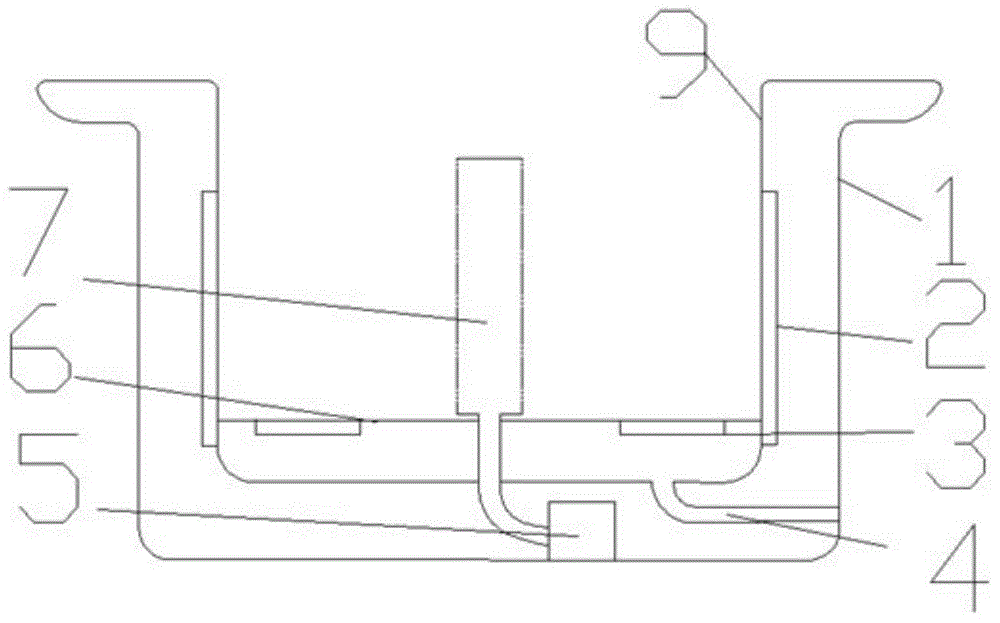
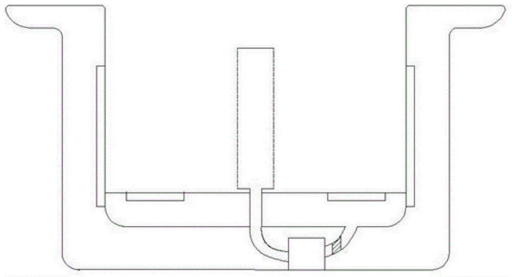
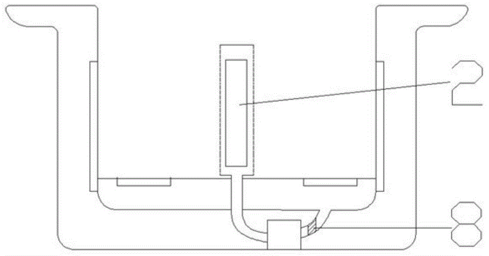
[0026] The ultrasonic cleaning machine includes an ultrasonic device 2, a cleaning tank 9, and an ultrasonic cleaning machine housing 1, wherein the cleaning tank 9 is located inside the ultrasonic cleaning machine housing 1, and the ultrasonic device 2 is fixed on the outer wall of the cleaning tank 9, and also includes a high-pressure water flow device. The high-pressure water flow device includes a high-pressure water spray device 7 and a high-pressure pump 5, the high-pressure water spray device 7 is located in the middle of the cleaning tank 9, and the high-pressure pump 5 is located below the cleaning tank 9 and connected to the high-pressure water spray device 7.

[0027] Wherein, the high-pressure water spraying device 7 is cylindrical.

[0028] Wherein, the side wall of the high-pressure water spray device 7 has uniformly distributed water spray holes.

[0029] Wherein, the diameter of the spray hole is 100um.

[0030] The ultrasonic cleaning machine also includes a ...

Embodiment 2

[0033] The ultrasonic cleaning machine includes an ultrasonic device 2, a cleaning tank 9, and an ultrasonic cleaning machine housing 1, wherein the cleaning tank 9 is located inside the ultrasonic cleaning machine housing 1, and the ultrasonic device 2 is fixed on the outer wall of the cleaning tank 9, and also includes a high-pressure water flow device. The high-pressure water flow device includes a high-pressure water spray device 7 and a high-pressure pump 5, the high-pressure water spray device 7 is located in the middle of the cleaning tank 9, and the high-pressure pump 5 is located below the cleaning tank 9 and connected to the high-pressure water spray device 7.

[0034] Wherein, the high-pressure water spraying device 7 is cylindrical.

[0035] Wherein, the side wall of the high-pressure water spray device 7 has uniformly distributed water spray holes.

[0036] Wherein, the diameter of the spray hole is 2mm.

[0037] The ultrasonic cleaning machine also includes a vi...


PUM


Abstract

The invention belongs to the field of ultrasonic cleaning and particularly provides an ultrasonic cleaning machine. The ultrasonic cleaning machine comprises an ultrasonic device, a cleaning tank, an ultrasonic cleaning machine shell, wherein the cleaning tank is located inside the ultrasonic cleaning machine shell, and the ultrasonic device is fixed to the outer wall of the cleaning tank. The ultrasonic cleaning machine further comprises a high-pressure water flow device, wherein the high-pressure water flow device comprises a high-pressure water flow water-spraying device and a high-pressure pump, the high-pressure water flow water-spraying device is located at the middle position of the inside of the cleaning tank, and the high-pressure pump is located under the cleaning tank and is connected with the high-pressure water flow water-spraying device. Therefore, the purpose of improving the cleaning capacity of the ultrasonic cleaning machine is achieved while the ultrasonic cleaning machine fully utilizes space, and the ultrasonic cleaning machine can be widely applied to cleaning of various workpieces.

Description

technical field [0001] The invention belongs to the field of ultrasonic cleaning, in particular to an ultrasonic cleaning machine. Background technique [0002] The ultrasonic waves propagate in the liquid, so that the liquid and the cleaning tank vibrate together at the ultrasonic frequency. When the liquid and the cleaning tank vibrate, they have their own natural frequency. This vibration frequency is the sound wave frequency, so people hear humming. The high-frequency oscillating signal sent by the ultrasonic generator is converted into high-frequency mechanical oscillation by the transducer and propagated into the medium-cleaning solvent. Thousands of tiny bubbles with a diameter of 50-500μm, the tiny bubbles existing in the liquid vibrate under the action of the sound field. These bubbles form and grow in the negative pressure area where the ultrasonic waves propagate longitudinally, while in the positive pressure area, when the sound pressure reaches a certain value,...

Claims


Application Information

Patent Timeline
Patent Type & Authority Applications(China)
IPC IPC(8): B08B3/12B08B3/02B08B3/14
CPCB08B3/02B08B3/12B08B3/14
Inventor 向延海
Owner XUZHOU ZHENFENG ULTRASONIC ELECTRONICS CO LTD
Why Eureka
Try Eureka