swing table
A workbench and swing oil cylinder technology, applied in workbenches, manufacturing tools, etc., can solve the problems of increased cost, inaccurate positioning, long exchange time, etc., and achieve the effect of increasing flexibility and scope of use
- Summary
- Abstract
- Description
- Claims
- Application Information
AI Technical Summary
Problems solved by technology
Method used
Image
Examples
specific Embodiment approach 1
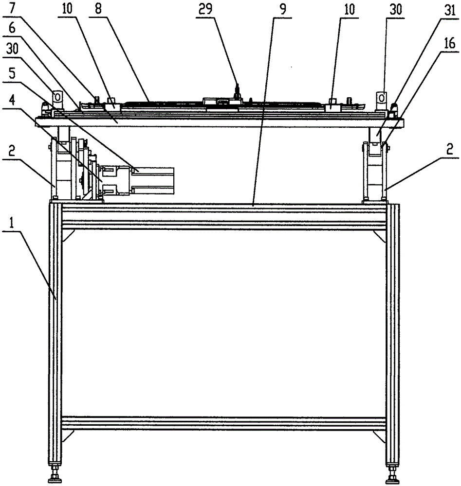
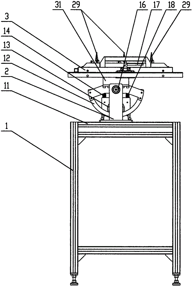
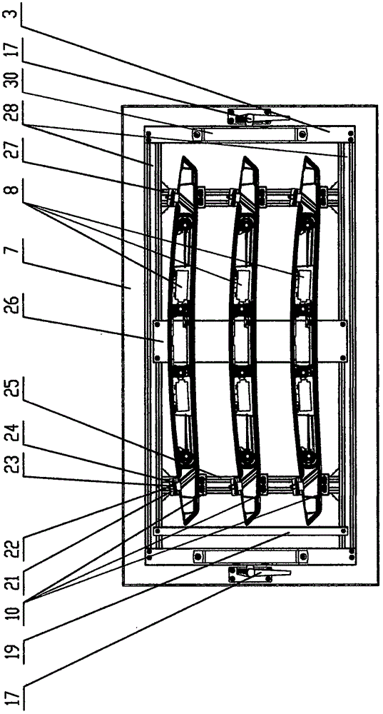
[0018] Specific implementation mode one: as Figure 1~3 As shown, a swing workbench includes a frame 1, a bracket 2, a reducer 4, and a motor 5, and is characterized in that: it also includes a gear A12, a gear B13, a swing table 6, a pulley 31, a sensor A14, a sensor B18, The clamping mechanism 21, the left and right brackets 2, and the reducer 4 are installed on the frame 1, the reducer 4 is connected to the motor 5, the gear B13 is set on the output shaft of the reducer 4, the gear A12 is fixedly connected with the connecting puller 31, The two connecting levers 31 are set on the bracket 2 through the rotating shaft 16, the swing table 6 and the connecting lever 31 are fixedly connected, and the gear A12 and the gear B13 are internally or externally engaged, which is shown as internal engagement in the figure;
specific Embodiment approach 2
[0019] Specific implementation mode two: as Figure 1~3 As shown, a swing table, the swing table 6 includes a vertical beam 3, a table 7, a locking handle 17, a positioning bar 19, a bottom plate A25, a bottom plate B26, a bottom plate C27, a frame 28, a handle 30, a vertical beam 3 and Frame 28 surrounds and synthesizes the square frame and table top 7 is connected, and bottom plate A25, bottom plate B26, bottom plate C27 and frame 28 are connected; Swing table 6 drives gear A12, gear B13 to rotate under the drive of reducer 4, motor 5, makes the swing table The workpiece 8 on 6 swings or rotates, and the sensor A14 and sensor B18 are used to detect the swing angle of the table top 7. There is a positioning pin between the table top 7 and the connecting puller 31. When replacing the workpiece 8, it can be quickly realized by holding the handle 30, and then use The locking handle 17 is locked; the workpiece 8 is a car decorative lamp, and the shape is more complicated, and the...
specific Embodiment approach 3
[0020] Specific implementation mode three: as Figure 1~3 As shown, a swing workbench, the clamping mechanism 21 includes a positioning block 10, a small shaft 22, an elastic component 23, and a clamping block 24. The elastic component 23 and the clamping block 24 are mounted on the small shaft 22 to clamp The block 24 can expand and contract under the action of the elastic member 23, relying on the clamping block 24 to clamp the workpiece 8, the clamping mechanism 21 is fixed on the bottom plate A25 and the bottom plate C27, and each workpiece 8 has at least two or more clamping mechanisms 21; The positioning bar 19 contacts with the left side of the workpiece 8, the positioning block 10 contacts the underside of the workpiece 8, the upper surface of the base plate A25, the base plate B26, and the base plate C27 contacts the workpiece 8 bottom surface, and the workpiece 8 has been completely positioned. Other compositions and connections are the same as those in Embodiments 1...
PUM
 Abstract
Description
Claims
Application Information
 - R&D
- Intellectual Property
- Life Sciences
- Materials
- Tech Scout
- Unparalleled Data Quality
- Higher Quality Content
- 60% Fewer Hallucinations
Browse by: Latest US Patents, China's latest patents, Technical Efficacy Thesaurus, Application Domain, Technology Topic, Popular Technical Reports.
© 2025 PatSnap. All rights reserved.Legal|Privacy policy|Modern Slavery Act Transparency Statement|Sitemap|About US| Contact US: help@patsnap.com


