
Heat-shrinkable tube clamp mechanism and heat-shrinkable tube positive compression expansion device using the same

A heat-shrinkable tube and positive pressure expansion technology, which is applied in the field of heat-shrinkable tube processing equipment, can solve the problems of broken heat-shrinkable tubes, inconsistent axial length of heat-shrinkable tubes, and uneven heating, so as to achieve uniform heating and reduce energy consumption. The effect of high consumption and thermal efficiency

Active Publication Date: 2018-07-17
深圳市智豪特材科技有限公司
View PDF4 Cites 0 Cited by
  • Summary
  • Abstract
  • Description
  • Claims
  • Application Information

AI Technical Summary

Problems solved by technology

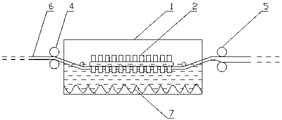
This method of immersing the heat-shrinkable tube in the hot liquid with the perforated iron oil bath tube can solve the technical problem of uneven heating caused by the heat-shrinkable tube floating on the liquid surface, but there is a problem that the heat-shrinkable tube is in the iron oil bath. The inside of the tube is heated and becomes soft, and there is no traction force during the axial movement process. It is easy to stretch the softened heat-shrinkable tube, which causes the stretching of the heat-shrinkable tube in the axial direction. The tube wall of some pulling parts is relatively thin, and more seriously, there will be fracture defects of the heat-shrinkable tube, and it does not meet the requirement of thermal processing for the axial length of the heat-shrinkable tube to remain unchanged.

Method used


Image

  • Heat-shrinkable tube clamp mechanism and heat-shrinkable tube positive compression expansion device using the same
  • Heat-shrinkable tube clamp mechanism and heat-shrinkable tube positive compression expansion device using the same
  • Heat-shrinkable tube clamp mechanism and heat-shrinkable tube positive compression expansion device using the same

Examples


Embodiment Construction

[0023] The present invention will be described in detail below in conjunction with the accompanying drawings and specific embodiments.

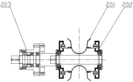
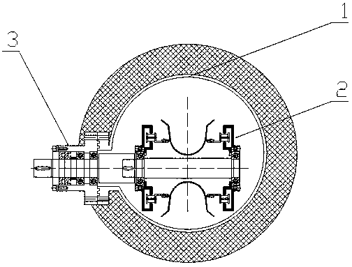
[0024] see figure 1 , the present invention provides a heat-shrinkable tube clamp mechanism 2, including several U-shaped clamps 201, a connecting mechanism 202 connecting the clamps 201, and a transmission mechanism 203 for driving the connecting mechanism 202, and several clamps in the clamp mechanism 2 201 are arranged in parallel into upper and lower layers, the U-shaped opening of the upper layer is upward, and the U-shaped opening of the lower layer is downward.

[0025] see figure 1 , in an embodiment of the clamp mechanism 2 of the present invention, horizontal steel bars are welded on the outer sides of each clamp 201. After the L-shaped steel bars in the connecting mechanism 202 are threaded, each clamp 201 is connected in parallel, and the connection The mechanism 202 moves reciprocatingly under the action of the transmission mec...


PUM


Abstract

The invention discloses a clamping mechanism and a heat shrink tubing positive companding device using the same. Compared with the spraying mode, the provided device can heat a heat shrink tubing more evenly, the thermal efficiency is higher, the required liquid temperature can be reduced by roughly 20 to 40 DEG C, the energy consumption is reduced, more importantly, the heat shrink tubing is completely soaked in the oil and is synchronously pulled out with the clamp, the wall of the heat shrink tubing is uniform, and no beveled edge is generated in the cross section. In the conventional method, a heat shrink tubing is soaked in hot liquid in an iron oil-bath tube with an opening, while in the provided method, the clamping mechanism can pull the heat shrink tubing to move in the liquid, and thus the heated and soft heat shrink tubing will not be pulled upwards.

Description

technical field [0001] The invention relates to heat-shrinkable tube processing equipment, in particular to a heat-shrinkable tube clamp mechanism and a heat-shrinkable tube positive pressure expansion device using the clamp mechanism. Background technique [0002] Heat-shrinkable tubes are widely used, and they are very important in the connection wires, wires, cables, etc. of electronic equipment that people come into contact with in daily life. [0003] Before the heat-shrinkable tube is applied to the end product, it needs to be heated to expand the diameter of the tube so that the tube wall can be changed from thick to thin. The traditional heating expansion is to spray 150-180°C liquid on the heat-shrinkable tube in a closed box, such as glycerin, ethylene glycol, etc. When this kind of heating expansion is in progress, the heat-shrinkable tube floats on the surface of the liquid to receive the spray. [0004] The traditional positive pressure expansion of heat-shrink...

Claims


Application Information

Patent Timeline
Patent Type & Authority Patents(China)
IPC IPC(8): B29C55/24B29C31/00B29C35/04
Inventor 文先衡周通王睿
Owner 深圳市智豪特材科技有限公司
Learn More