Intelligent electric phase separation device of alternating current electrified railway
A technology for electrified railways and electric phase separation, applied in power lines, transportation and packaging, vehicle components, etc., can solve problems such as locomotives breaking into phases with electricity, affecting the safety of the traction power supply system and driving order, and losing power in the neutral zone. Achieve the effect of controlling the switching time accurately, avoiding the interference between devices and man-made, and improving the reliability
- Summary
- Abstract
- Description
- Claims
- Application Information
AI Technical Summary
Problems solved by technology
Method used
Image
Examples
Embodiment 1
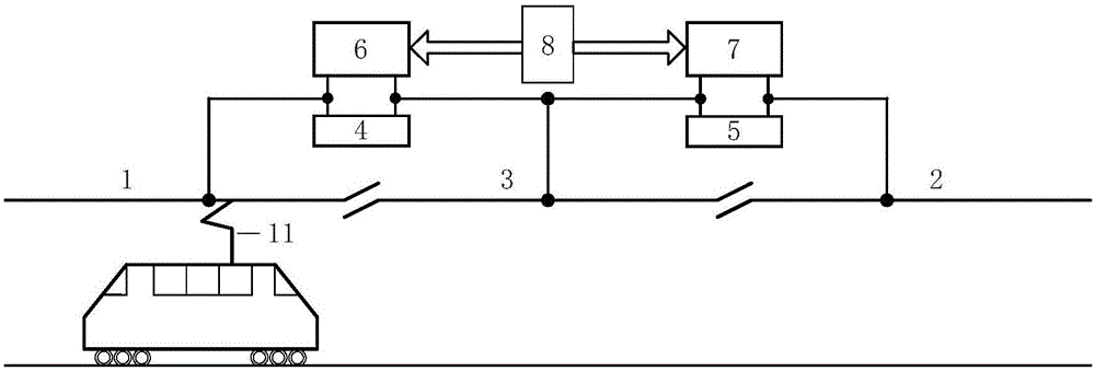
[0020] see figure 1 , the AC electrified railway locomotive intelligent electric phase-splitting device of the present invention comprises a first impedance 4, a second impedance 5, a first switch 6, a second switch 7 and a controller 8; after installing a current sensor in the first switch 6, it is connected with the first One impedance 4 is connected in parallel, and a current sensor is installed in the second switch 7 and connected in parallel with the second impedance 5; one end of the first switch 6 is connected to the first power supply arm 1 and a voltage sensor, the first switch 6 is installed on this node The other end of the second switch 7 is connected to the phase separation area 3 and a voltage sensor is installed on this node, and the other end of the second switch 7 is connected to the second power supply arm 2 and a voltage sensor is installed on this node. voltage sensor.
[0021] The voltage and current sensors installed in the above device and the control s...
Embodiment 2
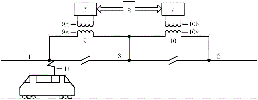
[0023] see figure 2 , the AC electrified railway locomotive intelligent electrical phase splitting device of the present invention includes a first switch 6, a second switch 7, a controller 8, a first transformer 9 and a second transformer 10; wherein, the first transformer 9 includes a first high voltage winding 9a and first low-voltage winding 9b, the second transformer 10 includes a second high-voltage winding 10a and a second low-voltage winding 10b, the first switch 6 is connected to both ends of the first low-voltage winding 9b, and the second switch 7 is connected to the second low-voltage winding 9b. Both ends of the winding 10b are connected; the first high voltage winding 9a is respectively connected to the first power supply arm 1 and the phase splitting area 3, and the second high voltage winding 10a is connected to the second power supply arm 2 and the phase splitting area 3 respectively. The required current sensor and voltage sensor can be installed on the firs...
PUM
 Abstract
Description
Claims
Application Information
 - R&D
- Intellectual Property
- Life Sciences
- Materials
- Tech Scout
- Unparalleled Data Quality
- Higher Quality Content
- 60% Fewer Hallucinations
Browse by: Latest US Patents, China's latest patents, Technical Efficacy Thesaurus, Application Domain, Technology Topic, Popular Technical Reports.
© 2025 PatSnap. All rights reserved.Legal|Privacy policy|Modern Slavery Act Transparency Statement|Sitemap|About US| Contact US: help@patsnap.com


