
Overrunning clutch device used in vehicle

An overrunning clutch and clutch technology, applied in clutches, one-way clutches, mechanical equipment, etc., can solve the problems of large energy transmission loss, large energy loss, and easy wear and tear of components, and achieve energy saving, simple manufacturing process, and mechanism. Safe and reliable effect

Inactive Publication Date: 2009-05-27
梁羽翔
View PDF6 Cites 0 Cited by
  • Summary
  • Abstract
  • Description
  • Claims
  • Application Information

AI Technical Summary

Problems solved by technology

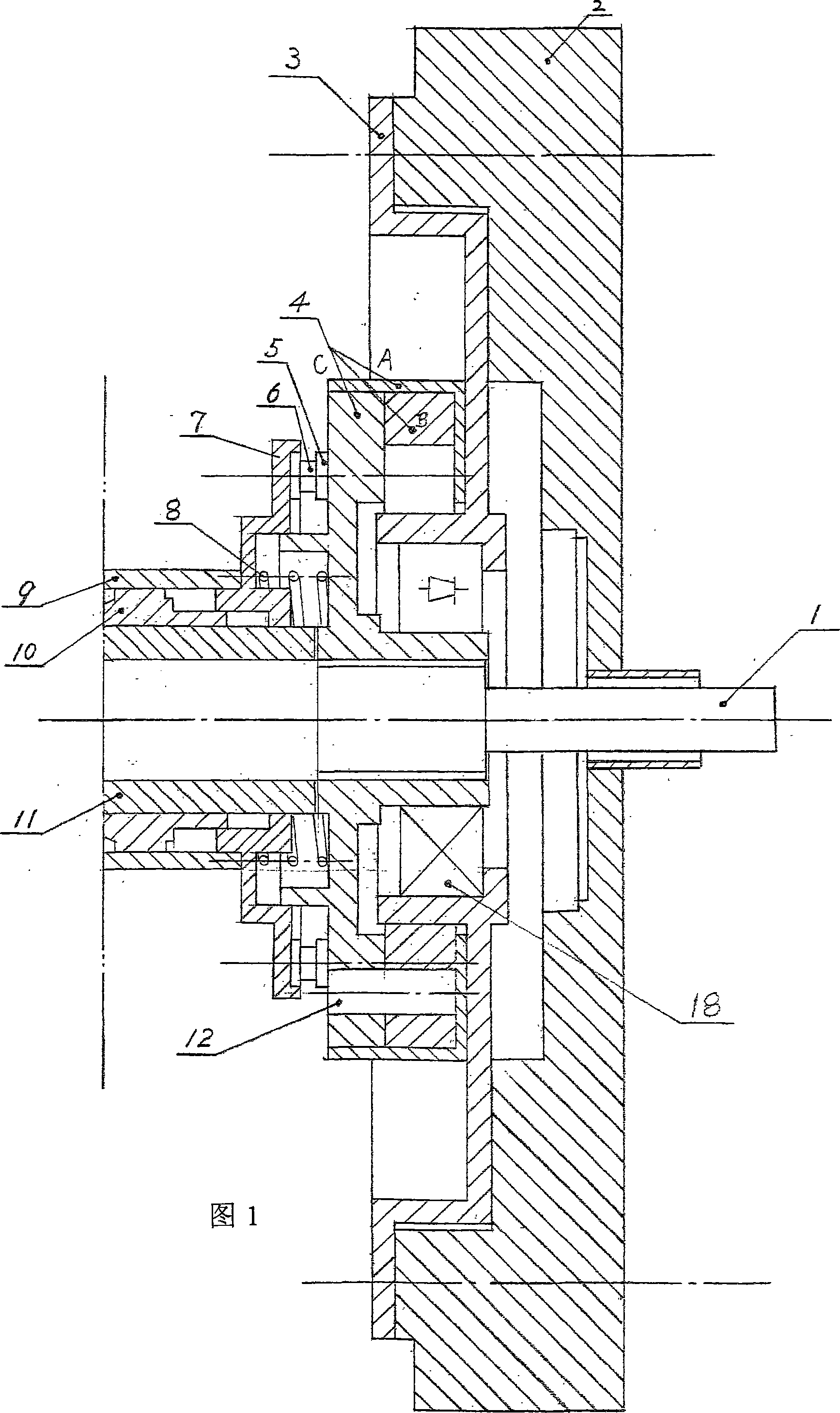
The ordinary overrunning clutch device is shown in Figure 1, which includes an active counterclockwise rotating shaft slidingly connected through a large roller embedded in the base, the large roller is slidingly connected to the top post, and the other end of the top post is connected to the return spring. The other end of the return spring is connected to the outer circumference of the base. This kind of ordinary overrunning clutch can only clutch. Although there is almost no loss of energy in the transmission torque, it cannot be clutched as needed; for friction clutches, not only the energy loss is great Large, and the number of revolutions is lost, it is no longer used in the structure that generally requires precision; the slider clutch, in the process of clutching, must be shut down and then clutched, and it is difficult to shift gears during clutching and there is a knocking sound. It is easy to wear and tear, and is generally used in automobile transmission. Although it has these shortcomings, it is still used in automobiles because of the small energy loss and no loss of revolutions after the gear is engaged; although the interdigital clutch is easy to operate the clutch , but itself is easily damaged, and the energy transmission loss is relatively large. The utility model patent "flip-push sliding rod type overrunning clutch device" applied by the applicant on March 16, 2005, its patent number is: 200520078462.1) also has a certain defect in the above-mentioned

Method used


Image

  • Overrunning clutch device used in vehicle
  • Overrunning clutch device used in vehicle
  • Overrunning clutch device used in vehicle

Examples


Embodiment Construction

[0009] Accompanying drawing is embodiment of the present invention.

[0010] Below in conjunction with appending the content of the present invention is further described:

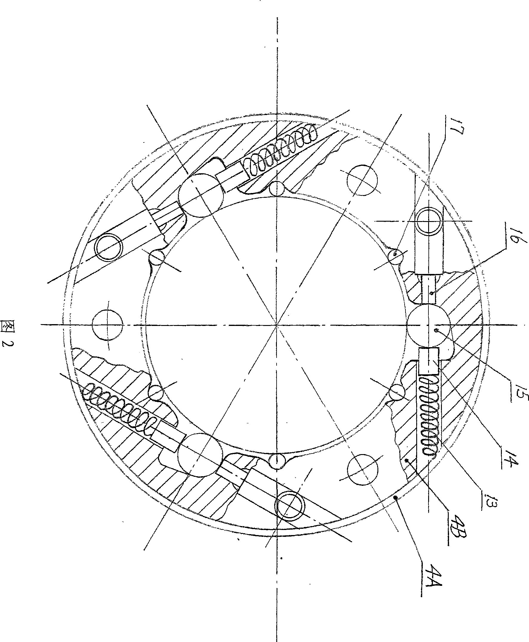
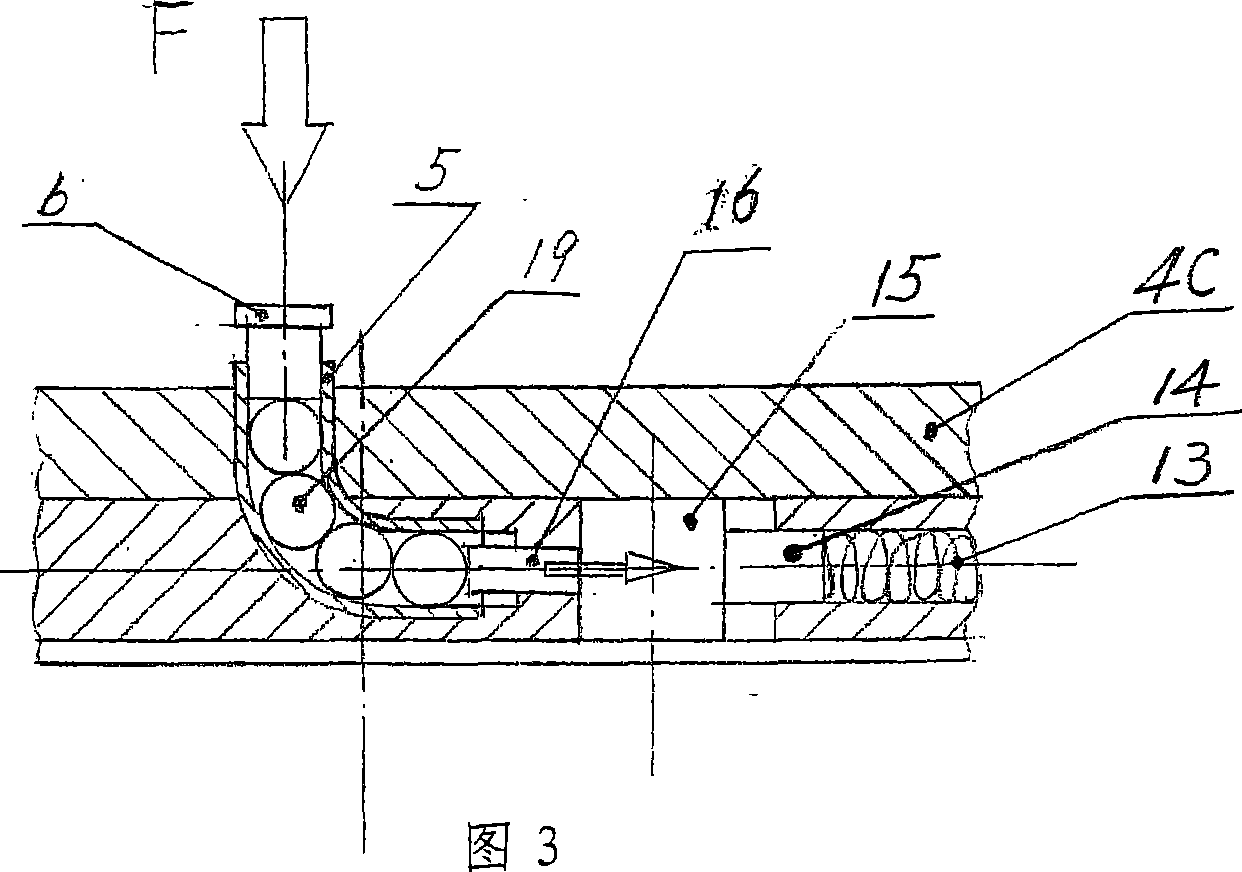
[0011] With reference to Fig. 1, Fig. 2, shown in Fig. 3, a kind of overrunning clutch device for automobile, comprises motor for automobile, and motor drives flywheel 2 to rotate, and the rotating disc 3 that is fastened on the flywheel 2 outputs with the same power, and the rotating circle The central shaft sleeve 11 of the disc 3 is set on the outer ring of the bearing 18. The clutch disc 4B in the clutch device is driven by the overrunning roller 15 under the action of the spring components 13 and 14, and the central shaft of the disc 3 drives the clutch disc. At least four small rollers 17 arranged on the inner circumference of 4B rotate accordingly; the toothed keyboard 4C fixed on the inner ring of the bearing 18 is driven by three pins 12 to rotate, and the inner cavity of the guide tube seat 9 is ...


PUM


Abstract

The invention discloses an overrun clutch device for automobile. Flywheel is drove by electric engine. The central axle bush of rotary disk is sleeved outside external ring of bearing. Clutch roller drives overrun roller and the central axle bush of rotary disk drives clutch roller. Dowel drives tooth keyset fixed in the inner circle of axletree and the transmission shaft rotating. Pin-lift of clutch pedal drives sliding bearing block and impels disk moving ahead. Clutch ring, overrun roller, spring module and tooth keyset are integrated by a cylinder cavity. Commutator impels ball module rotating in pipe. Pin-lift jogs the overrun roller translating to avoid its slant sticking the roller. When feet leaving the pin-lift of clutch pedal, the clutch gets back to its primary state under the effect of spring module. It has simple and compact structure and high sensitivity without loosing rotate speed, applies power commutator without moment dissipation, gas pollution or noise, saves energy. It can be applied in industries of automobile, motorcycle and machine tool etc.

Description

technical field [0001] The invention relates to a clutch device, in particular to an overrunning clutch device for automobiles. Background technique [0002] The clutch device used in the prior art mainly contains friction clutch device, slipper clutch device, interdigital clutch device, and common overrunning clutch device. The ordinary overrunning clutch device is shown in Figure 1, which includes an active counterclockwise rotating shaft slidingly connected through a large roller embedded in the base, the large roller is slidingly connected to the top post, and the other end of the top post is connected to the return spring. The other end of the return spring is connected to the outer circumference of the base. This kind of ordinary overrunning clutch can only clutch. Although there is almost no loss of energy in the transmission torque, it cannot be clutched as needed; for friction clutches, not only the energy loss is great Large, and the number of revolutions is lost,...

Claims


Application Information

Patent Timeline
Patent Type & Authority Patents(China)
IPC IPC(8): F16D41/064
Inventor 梁羽翔梁伟梁岳
Owner 梁羽翔
Learn More