Design method of flap driving mechanism and flap driving mechanism

A technology of driving mechanism and design method, which is applied in the field of flight control, can solve the problems of low efficiency of driving mechanism, achieve the effect of convenient implementation, practical principle, and improved efficiency

Active Publication Date: 2015-11-11
XIAN AIRCRAFT DESIGN INST OF AVIATION IND OF CHINA
View PDF6 Cites 7 Cited by
  • Summary
  • Abstract
  • Description
  • Claims
  • Application Information

AI Technical Summary

Problems solved by technology

[0003] The purpose of the present invention is to provide a design method of a flap driving mechanism and a flap driving mechanism, so as to solve the problem that the use efficiency of the driving mechanism is low when the aircraft flap is deflected at a large load and a large angle

Method used


Image

  • Design method of flap driving mechanism and flap driving mechanism
  • Design method of flap driving mechanism and flap driving mechanism

Examples


Embodiment Construction

[0024] Reference will now be made in detail to the exemplary embodiments, examples of which are illustrated in the accompanying drawings. When the following description refers to the accompanying drawings, the same numerals in different drawings refer to the same or similar elements unless otherwise indicated.

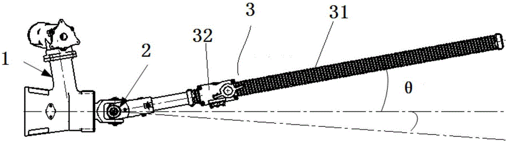
[0025] Such as Figure 1 to Figure 2 Shown, the design method of a kind of flap driving mechanism provided by the present invention is characterized in that, comprises:

[0026] Step 1. When the flap (not shown) is in the non-actuated state, and the drive shaft axis of the universal joint 2 coincides with the axis of the screw 31, define the universal joint 2 and the lead screw 31 here The state under the relative positional relationship is the first initial state.

[0027] Step 2, the flap rotates to a maximum set angle (usually prescribed), the lead screw 31 drives the driven shaft of the universal joint 2 to follow the flap to rotate the above maximum set angle, t...


PUM


Abstract

The invention relates to the field of flight control, in particular to a design method of a flap driving mechanism and the flap driving mechanism, and aims to solve the problem that the driving mechanism is low in use efficiency when an aircraft flap is loaded heavily and deflects a large angle. According to the design method of the flap driving mechanism, on the basis that a universal coupling is in an original state, a driven shaft is rotated by a preset angle around a hinge point in the anti-clockwise direction, and the current state of the universal coupling is used as the original state to be designed, so that the efficiency loss of the universal coupling is reduced when the flap is driven to rotate by the same angle, and the efficiency of the driving mechanism is greatly improved; meanwhile, on the premise that the external driving load of by the flap driving mechanism remains unchanged, the design load of the driving mechanism is reduced, the design weight of the driving mechanism is reduced, and the reliability of the driving mechanism is improved; the principle is simple and practical, and easy to implement.

Description

technical field [0001] The invention relates to the field of flight control, in particular to a design method of a flap driving mechanism and the flap driving mechanism. Background technique [0002] The flap drive mechanism is the actuator for flap movement. In the existing flap drive mechanism, the nut in the flap drive mechanism moves axially on the lead screw to push the flap to deflect around the flap rotation axis. At the same time, the lead screw and the The driven shaft of the universal joint is also deflected about its articulation. As the deflection angle of the lead screw increases gradually, the axial load on the lead screw will also increase, but the transmission efficiency of the mechanism will decrease accordingly. The existing flap drive mechanism is only suitable for small loads and small angles (the small angle at this time can be defined artificially: when the flaps are at the maximum angle, the axis of the drive shaft of the universal joint and the axis ...

Claims


Application Information

Patent Timeline
Patent Type & Authority Applications(China)
IPC IPC(8): B64C13/34
CPCY02T50/40
Inventor 陶刚王丽丽李志勇欧霞南海燕
Owner XIAN AIRCRAFT DESIGN INST OF AVIATION IND OF CHINA
Why Eureka
Try Eureka