High temperature and high pressure gate valve

A high-temperature and high-pressure, gate valve technology, applied in sliding valves, valve details, valve devices, etc., can solve the problem that high-temperature gate valves cannot meet high-pressure working conditions on site, and achieve the effect of reducing temperature, prolonging service life, and facilitating on-site installation.

Active Publication Date: 2018-01-16
NEWAY OIL EQUIP SUZHOU
View PDF7 Cites 1 Cited by
  • Summary
  • Abstract
  • Description
  • Claims
  • Application Information

AI Technical Summary

Problems solved by technology

[0005] In view of the defect that the existing high-temperature gate valve cannot meet the on-site high-pressure working conditions, the purpose of the present invention is to provide a high-temperature and high-pressure gate valve, which can meet the long-term use of the on-site production medium temperature -60°C-345°C, pressure ≤ 69MPa, Extends service life of high temperature seal components

Method used


Image

  • High temperature and high pressure gate valve
  • High temperature and high pressure gate valve
  • High temperature and high pressure gate valve

Examples


Embodiment Construction

[0024] Preferred embodiments of the present invention will be described in detail below in conjunction with the accompanying drawings.

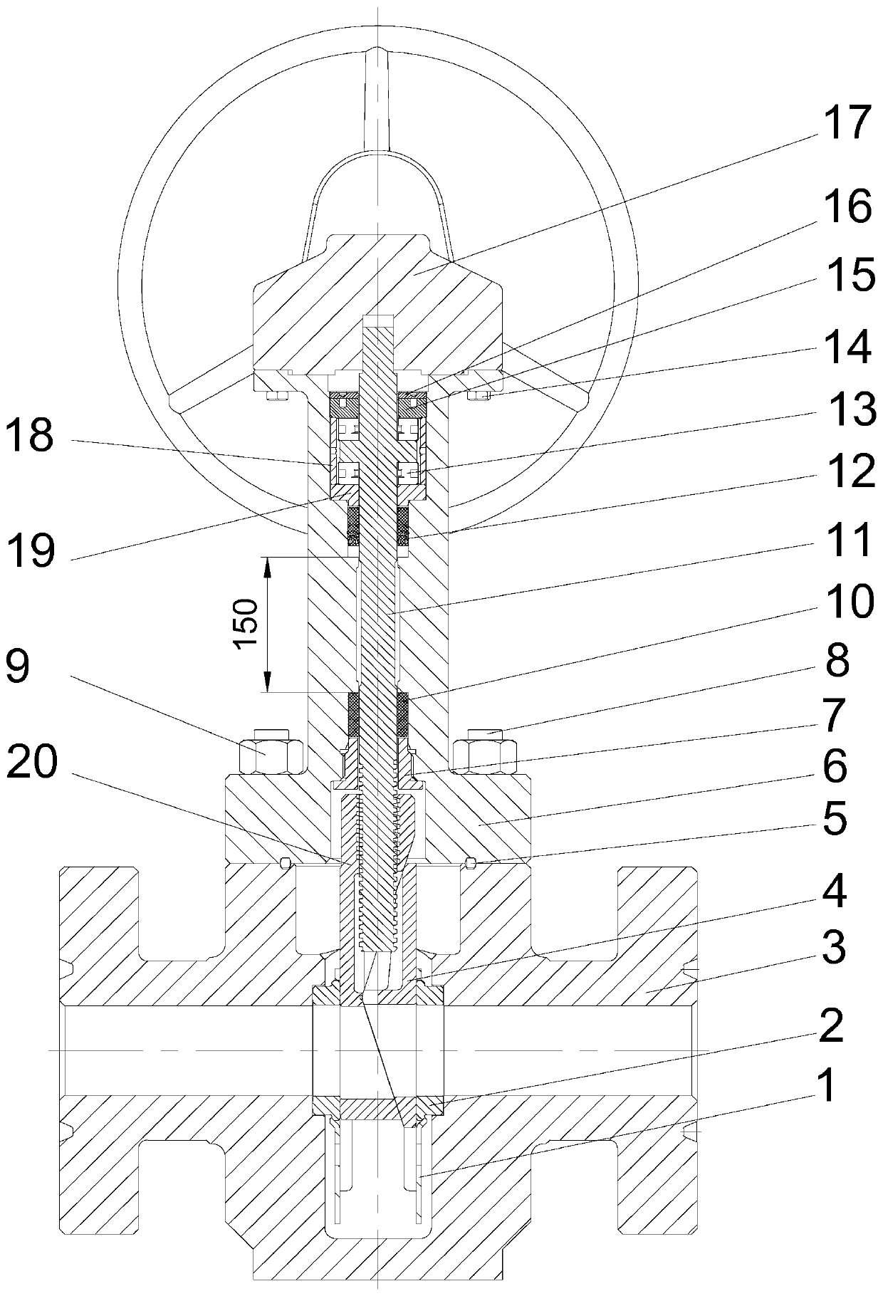
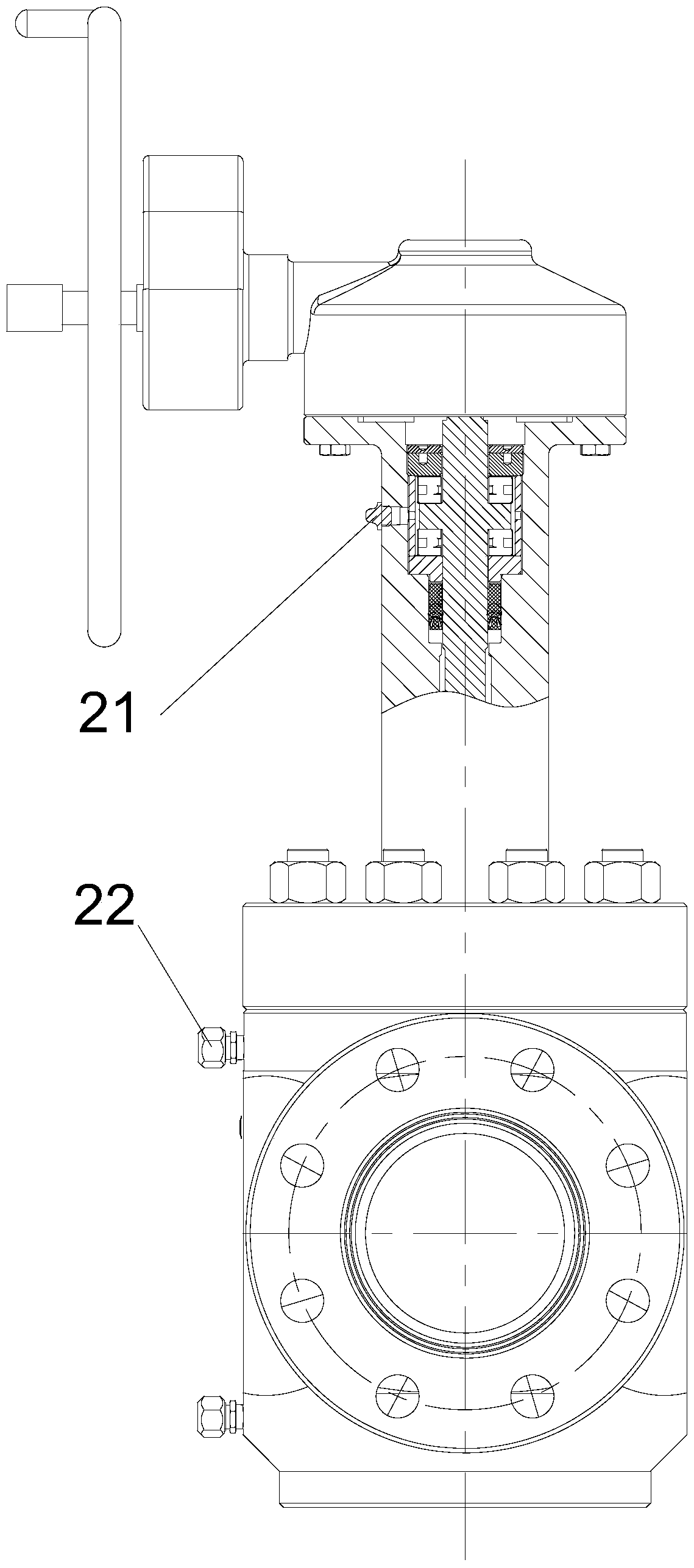
[0025] see Figures 1 to 3 , a high temperature and high pressure valve, a high temperature and high pressure gate valve, comprising a valve body 2, a valve seat 3, a gate plate 4, a valve cover 6, a valve stem 11 and a gear box 17 with a hand wheel.

[0026] The middle cavity of the valve body 3 is provided with a seat ring hole, and the valve seat 2 is installed in the seat ring hole with a clearance fit, and the valve seat 2 and the valve body 3 are sealed by metal.

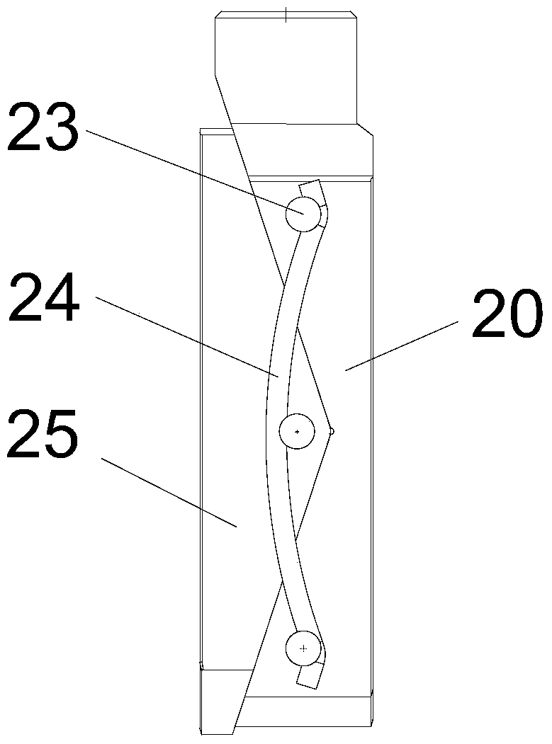
[0027] The guide plate 1 is fixed on the lower end of the valve seat 2 and extends downward. The flashboard 4 includes a main flashboard block 20 and a secondary flashboard block 25. The main flashboard block 20 cooperates with the secondary flashboard block 25 through an inclined surface and an elastic member is connected between the main flashboard block 20 and the seconda...


PUM


Abstract

The invention provides a high-temperature and high-pressure sluice valve which comprises a valve body, a valve seat, a wedge disc, a valve deck and a valve rod. The valve rod is rotationally arranged on the valve deck, and the lower portion of the valve rod is in threaded connection with the wedge disc. A first sealing assembly in sealing connection with the valve rod is arranged in a lower opening of the valve deck, and a second sealing assembly in sealing connection with the valve rod is arranged in an upper opening of the valve deck. The valve rod is rotationally supported in the valve deck through a bearing arranged above the second sealing assembly. According to the high-temperature and high-pressure sluice valve, the structure of the double sealing assemblies is adopted; by means of buffering of the first sealing assembly, the impact of working media on the second sealing assembly is greatly lowered, and therefore the sealing function can be effectively achieved through the second sealing assembly; and furthermore, the service life of the second sealing assembly is prolonged, and the working pressure value of the valve is increased.

Description

technical field [0001] The invention relates to a high-pressure gate valve, in particular to a high-temperature and high-pressure gate valve suitable for use in oil and natural gas exploitation. Background technique [0002] The high-temperature and high-pressure gate valves in thermal recovery industries such as oil and natural gas must be able to achieve long-term use in the working conditions of on-site production medium temperature -60°C-345°C and pressure ≤10000psi (69MPa). While the traditional high temperature gate valve can be used in the temperature range of -60°C-345°C, the working pressure must be ≤42MPa, so it cannot meet the requirements of high-pressure working conditions (pressure ≤69MPa). [0003] The bonnet of the traditional high-temperature gate valve only uses a single high-temperature-resistant sealing component to seal the valve stem. During the valve switch process, the medium in the pipeline enters the middle cavity and has a huge impact on the high-t...

Claims


Application Information

Patent Timeline
Patent Type & Authority Patents(China)
IPC IPC(8): F16K3/02F16K3/30F16K27/12
CPCF16K3/029F16K3/30F16K27/12
Inventor 王浩张佳王小英
Owner NEWAY OIL EQUIP SUZHOU
Why Eureka
Try Eureka