Eureka AIR delivers breakthrough ideas for toughest innovation challenges, trusted by R&D personnel around the world.

An uninterrupted gas supply device on a circular production line

A gas supply device and production line technology, which can be applied to equipment loaded into pressure vessels, gas/liquid distribution and storage, container discharge methods, etc. , reduce costs, avoid the effect of mobile synchronization

Active Publication Date: 2017-05-17
ANHUI KINGPOWER EQUIP & MOLD MFR
View PDF5 Cites 0 Cited by
  • Summary
  • Abstract
  • Description
  • Claims
  • Application Information

AI Technical Summary

Problems solved by technology

Since the air supply interface usually involves sealing issues, it usually takes a certain amount of time to plug and unplug the air supply interface, which not only consumes manpower, but also wastes man-hours

Method used


Image

  • An uninterrupted gas supply device on a circular production line
  • An uninterrupted gas supply device on a circular production line
  • An uninterrupted gas supply device on a circular production line

Examples


Embodiment Construction

[0020] The present invention will be described in further detail below in conjunction with the accompanying drawings.

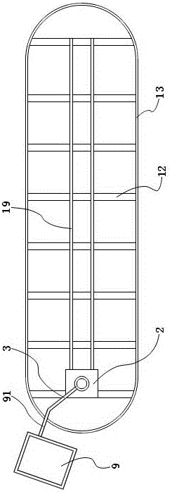
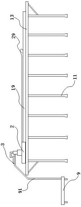
[0021] like figure 1 , figure 2 As shown, an uninterrupted gas supply device on an annular production line includes an annular frame and a production trolley 9 . The ring frame includes a column 11 , a beam 12 and a ring edge 13 . Column 11 is vertically installed. The beam 12 is installed on the top of the column 11 and is horizontal. The ring edge 13 is mounted on the end of the beam 12 to form a ring edge structure. The central frame of the ring frame is provided with a guide rail 19 . The guide rail 19 is a linear guide rail and is installed on the beam 12 . Air supply car 2 is provided on the guide rail 19 . The air supply vehicle 2 can move along the guide rail 19 . There are a plurality of production trolleys 9, which can move in a circular direction around the ring frame. One of the production trolleys 9 is equipped with an air supply connec...


PUM


Abstract

The invention discloses an uninterrupted air supply device on a circular production line, which comprises a circular frame and a production trolley. The production trolley is movable in a circular direction around the ring frame. The center frame of the ring frame is provided with guide rails. An air supply car is provided on the guide rail. The air supply vehicle can move along the guide rail. The air supply connecting arm is installed on the production trolley. A rotary air supply device is installed on the air supply vehicle. The rotary air supply device can rotate 360 ​​degrees on the horizontal plane. The rotary air supply device is connected with the air supply connecting arm. When the production trolley moves around the ring frame, the production trolley can drag the air supply vehicle along the guide rail through the air supply connecting arm and the rotating air supply device. The invention can continuously supply air to the production trolley through the rotating air supply device.

Description

technical field [0001] The invention relates to an air supply device on a circular production line. Background technique [0002] The circular production line is a production line with a common structure. If each station of the production line needs to use air supply, the product to be processed usually needs to repeatedly plug and unplug the air supply interface at each station. Since the air supply interface usually involves sealing issues, it usually takes a certain amount of time to plug and unplug the air supply interface, which not only consumes manpower, but also wastes man-hours. Contents of the invention [0003] The problem to be solved by the present invention is to avoid the need to plug and unplug the air supply interface in different stations of the circular production line. [0004] In order to solve the above problems, the scheme adopted by the present invention is as follows: [0005] An uninterrupted gas supply device on a circular production line, com...

Claims


Application Information

Patent Timeline
Patent Type & Authority Patents(China)
IPC IPC(8): F17C5/06F17C13/00
Inventor 宗海啸段宗军
Owner ANHUI KINGPOWER EQUIP & MOLD MFR
Why Eureka
Eureka Blog
Learn More