An evaporating tube rotary cutting device

A technology of rotary cutting and evaporating tubes, which is applied in metal processing and other directions, and can solve problems such as uneven cutting

Active Publication Date: 2017-03-29
ANHUI KINGPOWER EQUIP & MOLD MFR
View PDF10 Cites 0 Cited by
  • Summary
  • Abstract
  • Description
  • Claims
  • Application Information

AI Technical Summary

Problems solved by technology

[0003] The problem to be solved by the present invention: the evaporating tube cutting mechanism in the prior art causes the cut to be uneven

Method used


Image

  • An evaporating tube rotary cutting device
  • An evaporating tube rotary cutting device
  • An evaporating tube rotary cutting device

Examples


Embodiment Construction

[0017] The present invention will be described in further detail below in conjunction with the accompanying drawings.

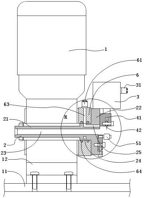
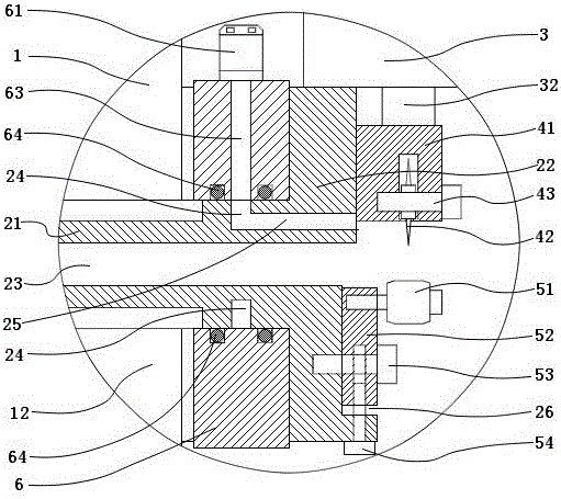
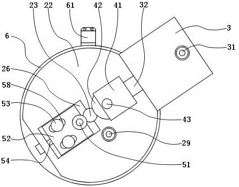
[0018] Such as figure 1 , figure 2 , image 3 As shown, a rotary cutting device for evaporating tubes includes a motor 1, a rotary guide body 2, a blade 42, a pneumatic radial pushing mechanism, a cutting support mechanism, and a rotary air supply mechanism. The rotating guide body 2 is an integrated structure composed of a pipe body 21 and an annular disk 22 . The rotating guide body 2 and the motor 1 are installed on the frame 12 . The frame 12 is fixed on the platform 11 . The rotating guide body 2 is connected with the motor 1 and can rotate around its central axis driven by the motor 1 . A tube hole 23 is provided on the central axis of the rotating guide body 2 . The tube hole 23 is used to support the straightened evaporation tube. The annular disc 22 is located at one end of the tube body 21 and is coaxial with the tube body 21 . The pneumati...


PUM


Abstract

The invention discloses a rotary cutting device for evaporation tubes, which comprises a motor, a rotary guide body, a blade, a pneumatic radial pushing mechanism, a cutting support mechanism, and a rotary air supply mechanism. The rotating guide body is an integrated structure composed of a tube body and a ring disc, and a tube hole is arranged on the central axis. The rotating guide body can rotate under the drive of the motor. The pneumatic radial pushing mechanism, the cutting supporting mechanism and the blade are installed on the rotating guide body and can rotate with the rotating guide body. The pneumatic radial pushing mechanism is used to drive the blade to move radially on the ring disc. The rotary air supply mechanism is used to provide compressed gas for the operation of the cylinder when the cylinder rotates with the rotary guide body. When the invention works, the blade rotates around the axis of the evaporation tube to cut off the evaporation tube, so that when the evaporation tube is cut off, the incision is relatively smooth, and the blade is pushed to the center of the evaporation tube, even if a burr is generated, it is toward the inside of the evaporation tube. This will not affect the front connection installation after evaporation.

Description

technical field [0001] The invention relates to a rotary cutting device, in particular to an automatic rotary cutting device for evaporation tubes. Background technique [0002] CN2614095 discloses a "automatic bile wrapping machine for inner bile evaporating tubes of refrigerators and freezers". The equipment is composed of a main shaft rotation mechanism, an axial feeding mechanism, a pipe material conveying mechanism and a control device. The pipe material conveying mechanism includes a straightening pipe conveying device. The straightening pipeline device involves an evaporation tube cutting mechanism. In this document, the disclosure of the evaporating tube cutting mechanism is not sufficient, and its specific structure can only be understood from the diagrams. According to the structure shown in FIG. 5 of this document, the rotary cutter 207 is composed of a cylinder 209 for pushing the rotary cutter 207, and the cylinder 209 is fixed on the base of the straightenin...

Claims


Application Information

Patent Timeline
Patent Type & Authority Patents(China)
IPC IPC(8): B26D1/34B26D7/00B26D7/26
Inventor 宗海啸李振霞方景红
Owner ANHUI KINGPOWER EQUIP & MOLD MFR
Why Eureka
Try Eureka