Built-in bottom-valve-free LNG pump well structure
A bottomless valve, built-in technology, applied in the container filling method, container discharge method, gas/liquid distribution and storage, etc., can solve the problem that the submersible pump cannot close the storage tank and connect the pump well, and the bottom valve cannot be opened at any time Problems such as maintenance and replacement, inconvenient maintenance personnel safety, etc., to achieve the effect of increasing equipment safety, improving energy efficiency, and implementing easy installation
- Summary
- Abstract
- Description
- Claims
- Application Information
AI Technical Summary
Problems solved by technology
Method used
Image
Examples
Embodiment 1
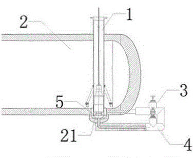
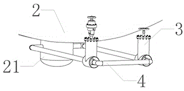
[0031] Such as figure 1 and figure 2 As shown, the structure of the built-in bottomless valve LNG pump well includes the pump well 1 arranged in the storage tank 2, the pump well 1 is provided with a submersible pump, the inner diameter of the pump well 1 matches the diameter of the submersible pump, and the submersible pump After being placed into the pump well, a liquid inlet chamber 5 is formed between the inlet end of the submersible pump and the bottom end of the pump well 1; the pump well 1 is provided with a number of pipelines 4 extending to the outside of the storage tank 2, and the number of pipelines 4 can be One, or two, or even more, one end of the pipeline 4 communicates with the liquid inlet chamber 5, and the other end of the pipeline 4 communicates from the outside of the storage tank 2 to the inside of the storage tank 2; the pipeline 4 is located outside the storage tank 2 A number of shut-off valves 3 are provided on the part, and the number of shut-off v...
Embodiment 2
[0033] Such as figure 1 and figure 2 As shown, the built-in bottomless valve LNG pump well structure, the bottom of the pump well 1 is a sealed structure, the pipeline 4 is connected to the liquid inlet chamber 5 on the bottom surface and / or side wall of the pump well 1, and the pipeline 4 can be connected to the liquid inlet chamber 5 from the pump well 1. The bottom enters and connects to the liquid inlet chamber 5, and can also be connected to the liquid inlet chamber 5 from the left or right side wall of the pump well 2, and the end of the pipeline 4 located outside the storage tank 2 is connected to the bottom surface of the storage tank 2; and / or the pipeline 4 One end located outside the storage tank 2 is connected to the side of the storage tank 2, the storage tank 2 is provided with an inner suction pipe connected to the pipeline 4, and the inner suction pipe extends to the inner bottom of the storage tank 2, and the pipeline 4 can be directly and / or indirectly It i...
Embodiment 3
[0035] Such as figure 1 and figure 2 As shown, the built-in bottomless valve LNG pump well structure, the bottom of the storage tank 2 is provided with a liquid accumulation pit 21, the LNG inside the storage tank 2 continuously flows to the liquid accumulation pit 21, and the bottom of the pump well 1 extends into the liquid accumulation pit 21, to ensure that the temperature remains constant and the temperature fluctuation range is minimal, the pipeline 4 is connected to the liquid accumulation pit 21 outside the storage tank 2, and at the same time, the bottom of the pump well extends into the liquid accumulation pit, which reduces the pipe length required for connecting the pipeline and saves materials .
PUM
 Abstract
Description
Claims
Application Information
 - R&D
- Intellectual Property
- Life Sciences
- Materials
- Tech Scout
- Unparalleled Data Quality
- Higher Quality Content
- 60% Fewer Hallucinations
Browse by: Latest US Patents, China's latest patents, Technical Efficacy Thesaurus, Application Domain, Technology Topic, Popular Technical Reports.
© 2025 PatSnap. All rights reserved.Legal|Privacy policy|Modern Slavery Act Transparency Statement|Sitemap|About US| Contact US: help@patsnap.com


