Anti-dazzle visual operating room shadowless lamp system

A shadowless lamp and operating room technology, applied in the field of medical equipment, can solve the problems of mutual influence, unclear camera, limited camera range, etc., and achieve the effect of satisfying temperature, good cold light effect, and convenient use

Inactive Publication Date: 2015-11-11
HUBEI FEIGOT MEDICAL TECH CO LTD
View PDF5 Cites 4 Cited by
  • Summary
  • Abstract
  • Description
  • Claims
  • Application Information

AI Technical Summary

Problems solved by technology

[0003] Traditional shadowless lamps generally include components such as a base, a display screen, a shadowless lamp, and a single camera. Most of the display screens, cameras, and shadowless lamps are connected to the base through pipe fittings to achieve multi-directional adjustment functions. There will be certain restrictions on adjusting the angle, for example, there are some surgical blind spots that cannot be modified. At the same time, the overall assembly of this cantilever is troublesome, and it is easy to get stuck during use.
On the other hand, the light source of the shadowless lamp is generally formed by direct downward light, which is easy to produce glare, which will cause impact on the surgeon's vision and affect the operation.
At the same time, the traditional shadowless lamp uses a single camera, which limits the shooting range, such as only partial shooting or large-scale shooting, which causes troubles for remote consultation, especially the light source of the shadowless lamp and the camera cannot be placed reasonably, and the two are likely to cause mutual influence, such as the brightness of the shadowless lamp lighting There are problems such as shadows and unclear camera, which bring inconvenience to actual use

Method used


Image

  • Anti-dazzle visual operating room shadowless lamp system
  • Anti-dazzle visual operating room shadowless lamp system
  • Anti-dazzle visual operating room shadowless lamp system

Examples


Embodiment Construction

[0031] Below in conjunction with accompanying drawing, the present invention will be further described:

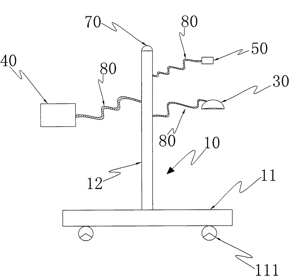
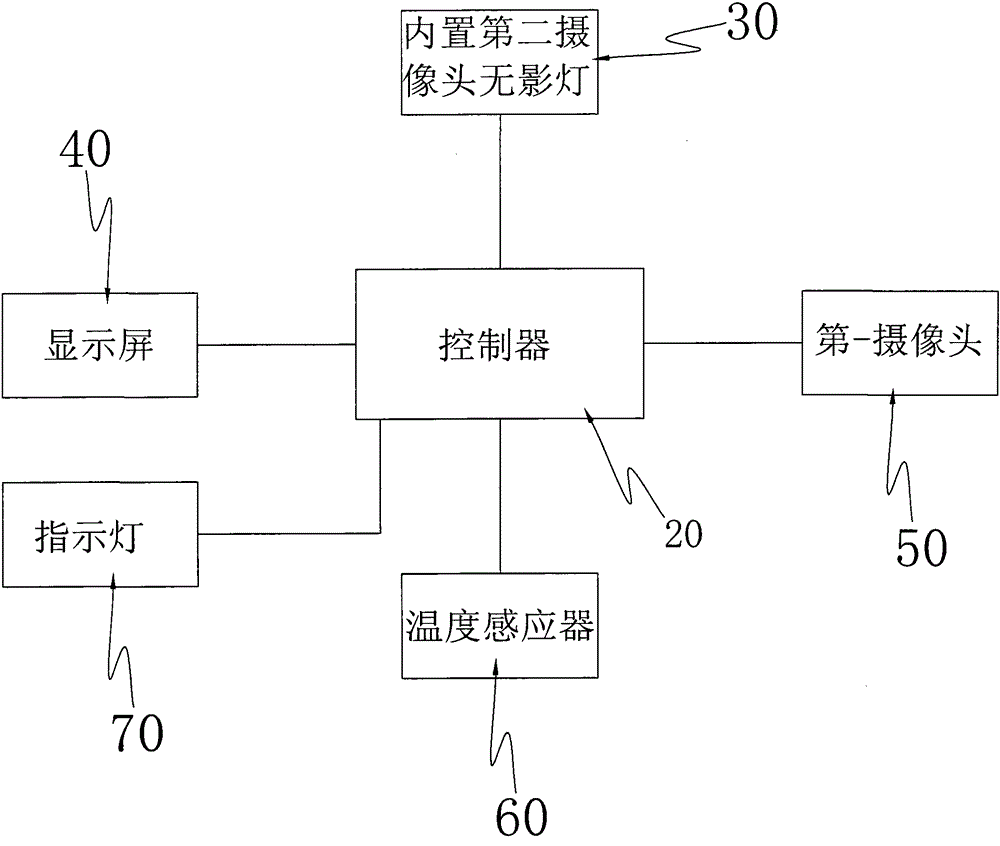
[0032] Such as Figure 1-3 As shown, an anti-glare visual operating room shadowless lamp system includes a base 10, a main controller 20, a shadowless lamp 30, a display screen 40, a first camera 50, a temperature sensor 60 and an indicator light 70, wherein:

[0033] The base 10 includes a base 11 and a support rod 12 installed vertically on the base, and the support rod 12 can be made of a metal pipe. The bottom of the base 11 is equipped with movable rollers 111, so that the whole device can be moved arbitrarily during use.

[0034] The main controller 20 is connected with the shadowless lamp 30, the display screen 40, the first camera 50, the temperature sensor 60, and the indicator light 70 to control the shadowless lamp 30, the display screen 40, the first camera 50, the temperature sensor 60, and the indicator light 70 works, the indicator light 70 is installed on...


PUM


Abstract

The invention discloses an anti-dazzle visual operating room shadowless lamp system. The anti-dazzle visual operating room shadowless lamp system comprises a substrate, a main controller, a shadowless lamp and a display screen, wherein the shadowless lamp and the display screen are connected with the main controller. The substrate is provided with a first camera. The shadowless lamp comprises a lampshade, an LED lamp, a second camera and a light-transmitting mirror installed on the bottom of the lampshade. The LED lamp is installed on the inner side wall of the lampshade to form an annular light source emitting light laterally. The second camera is installed in the lampshade and connected with the main controller. A cold light reflecting film is arranged on the inner side surface of the lampshade. The light-transmitting mirror is provided with an open hole facing the second camera, and an infrared filtering film is arranged on the outer surface of the light-transmitting mirror. Thus, the operation range can be extended by installing the multiple cameras, remote consultation can be promoted more effectively, the anti-dazzle effect can be achieved, impact to the vision of surgical doctors is avoided, the better cold light effect can be achieved, the requirement of the operating room temperature can be met, and infrared rays can be filtered out effectively.

Description

technical field [0001] The invention relates to the field of medical appliances, in particular to an anti-glare visible operating room shadowless lamp system. Background technique [0002] As we all know, the manual shadowless lamp is a necessary routine equipment in the operating room of the medical and health system. As a special lighting equipment, it plays a vital role for surgeons to perform operations. With the development of science and technology, surgical shadowless lamps with low temperature, shadowless, high brightness and high intelligence are favored by more and more surgeons. [0003] Traditional shadowless lamps generally include components such as a base, a display screen, a shadowless lamp, and a single camera. Most of the display screens, cameras, and shadowless lamps are connected to the base through pipe fittings to achieve multi-directional adjustment functions. There are certain restrictions on adjusting the angle. For example, there are some surgical ...

Claims


Application Information

Patent Timeline
Patent Type & Authority Applications(China)
IPC IPC(8): F21L2/00F21V33/00F21V19/00F21V3/04F21V9/04F21V21/06F21V23/00F21V21/32F21W131/205F21Y101/02
Inventor 彭世帅
Owner HUBEI FEIGOT MEDICAL TECH CO LTD
Why Eureka
Try Eureka