Jet refrigeration and active cooling beam combined applying system

A combined application and active technology, applied in applications, air conditioning systems, household heating, etc., can solve the problems of low energy efficiency of injection refrigeration, and achieve the effect of simple structure, low energy consumption, and simplified structure of air conditioning system

Active Publication Date: 2015-11-11
TONGJI UNIV
View PDF6 Cites 1 Cited by
  • Summary
  • Abstract
  • Description
  • Claims
  • Application Information

AI Technical Summary

Problems solved by technology

[0005] The purpose of the present invention is to provide a joint application system of jet refrigeration and active chilled beam technology with high refrigeration energy efficiency and simple structure in order to overcome the defect of low energy efficiency of current jet refrigeration

Method used


Image

  • Jet refrigeration and active cooling beam combined applying system
  • Jet refrigeration and active cooling beam combined applying system
  • Jet refrigeration and active cooling beam combined applying system

Examples


Embodiment

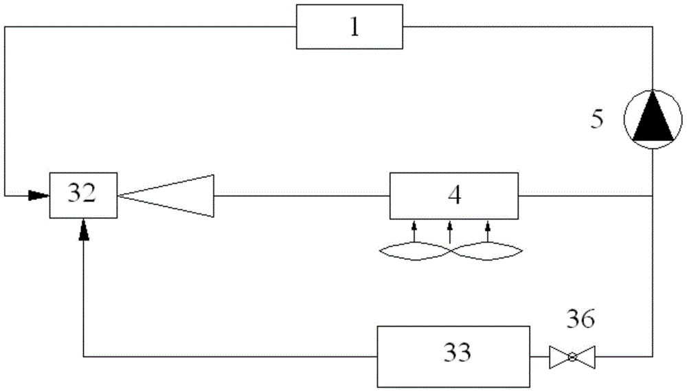
[0028] like figure 1 As shown, the end of the active chilled beam includes the end of the wind side of the chilled beam and the end of the water side of the chilled beam. After the treated primary air is sent to the active chilled beam, it is sprayed at high speed through the nozzle 22, and the high-speed airflow generates negative pressure in the mixing chamber 24, thereby inducing the indoor low-speed indoor air to pass through the orifice plate 26 and pass through the water side end of the chilled beam. The heat exchange coil 23 is cooled and mixed with the primary air belonging to the end of the wind side of the chilled beam, then forms an attached jet through two closed diversion grooves 25, and attaches and supplies air to the room along the suspended ceiling. The refrigerant temperature (16°C / 19°C) of the active chilled beam air-conditioning system is higher than that of the traditional air-conditioning system (7°C / 12°C).

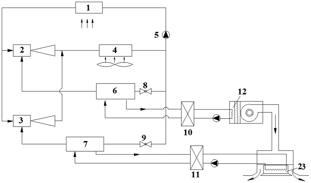
[0029] like figure 2 As shown, the traditio...


PUM


Abstract

The invention relates to a jet refrigeration and active cooling beam combined applying system which comprises a jet refrigeration subsystem and an active cooling beam subsystem. The jet refrigeration subsystem comprises a generator (1), a low-pressure ejector (2), a high-pressure ejector (3), a condenser (4), a water pump (5), a low-temperature side evaporator (6), a high-temperature side evaporator (7), a low-pressure throttling valve (8) and a high-pressure throttling valve (9). Outlet gas of the generator (1) is divided into two routes and enters the condenser (4). Outlet refrigerant of the condenser (4) enters the generator (1), the high-temperature side evaporator (7) and the low-temperature side evaporator (6) to complete refrigeration circulation. A cooling beam wind side tail end exchanges heat with the low-temperature side evaporator (6) through a low-temperature heat exchanger (10), and a cooling beam water side tail end exchanges heat with the high-temperature side evaporator (7) through a high-temperature heat exchanger (11). Compared with the prior art, the jet refrigeration and active cooling beam combined applying system has the advantages that the advantages of a cooling beam are brought into play, the structure is simple, the jet refrigeration evaporation temperature is increased, and the integrity of the system is high.

Description

technical field [0001] The invention relates to a spray refrigeration device, in particular to a combined application system of spray refrigeration and active chilled beams. Background technique [0002] Energy shortage and environmental pollution have become increasingly serious problems, and energy conservation and emission reduction have become the focus of people's increasing attention. Ejection refrigeration technology can use water and a variety of environmentally friendly refrigeration media as working fluids, driven by various forms of low-level heat sources (solar energy, geothermal energy, industrial waste heat, waste gas, and biomass energy, etc.) to achieve refrigeration. Because of its simple structure, long service life, low initial investment and low maintenance cost, jet refrigeration technology has attracted the attention of many scholars at home and abroad. However, due to the low energy efficiency of ejection refrigeration, it has not been well promoted a...

Claims


Application Information

Patent Timeline
Patent Type & Authority Applications(China)
IPC IPC(8): F24F5/00
CPCF24F5/0007F24F5/0046
Inventor 李岩学阮应君袁丽
Owner TONGJI UNIV
Why Eureka
Try Eureka