Numerical control machine tool rotating shaft error detection method based on binocular vision

A technology of binocular vision and CNC machine tools, which is applied to measuring devices, computer parts, instruments, etc., and can solve problems such as installation error detection and identification difficulties of the rotation axis of CNC machine tools

Active Publication Date: 2015-11-11
DALIAN UNIV OF TECH
View PDF7 Cites 34 Cited by
  • Summary
  • Abstract
  • Description
  • Claims
  • Application Information

AI Technical Summary

Problems solved by technology

At the same time, this method solves the problem of difficult detection and identification of the installation error of the rotation axis of the CNC machine tool, and provides a new direction for the error detection and identification technology of the machine tool

Method used


Image

  • Numerical control machine tool rotating shaft error detection method based on binocular vision
  • Numerical control machine tool rotating shaft error detection method based on binocular vision
  • Numerical control machine tool rotating shaft error detection method based on binocular vision

Examples


Embodiment Construction

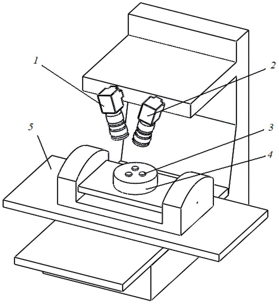
[0045] The specific embodiments of the present invention will be described in detail below in conjunction with the technical solutions and accompanying drawings. attached figure 1 It is a model diagram of a machine tool error detection device based on binocular vision. In the method, two left and right cameras 1 and 2 are used to collect coordinate information of coded marking points on the surface of the measured turntable, and after processing, the link error of the rotation axis is resolved and identified.

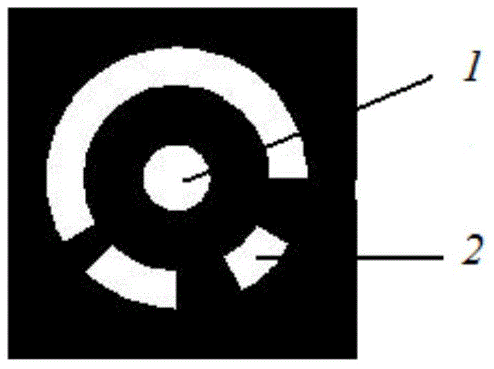
[0046] Install the measurement device first, install the left and right cameras 1 and 2 above the rotation axis, fix the left and right high-speed cameras 1 and 2, and adjust the position so that the measurement field of view is in the common field of view of the left and right high-speed cameras 1 and 2 Inside, adjust the brightness of the light source to increase the brightness of the measurement space; then, affix the reflective markers 3 on the surface of the turnt...


PUM


Abstract

The invention discloses a numerical control machine tool rotating shaft error detection method based on binocular vision, belongs to the machine tool precision detection technology field and relates to a double rotating shaft geometry error detection and identification method of a five-axes numerical control machine tool. The method adopts a high-resolution binocular vision system. Position information of a marking point which is pasted on a machine tool rotation table surface is collected. Through camera calibration, image segmentation, marking point extraction and a machine tool rotating shaft error identification model, detection acquisition of a two-position error and a two-angle error of a machine tool rotating shaft is realized. Rapid measurement of a geometrical parameter is completed. A circular marking point is used. An image processing program is simple, feature extraction precision is high, robustness is good and measurement is rapid and convenient. Simultaneously, a problem that numerical control machine tool rotating shaft installation error detection and identification are difficult is solved and a new direction is provided for a machine tool error detection and identification technology.

Description

technical field [0001] The invention belongs to the technical field of machine tool precision detection, and relates to a method for detecting and identifying geometric errors of two rotating shafts of a five-axis numerically controlled machine tool. Background technique [0002] In the fields of aviation, spaceflight and defense industry, the requirements for high-efficiency and high-precision manufacturing are getting higher and higher. Especially for engine impellers with complex structures, mold manufacturing and other parts, five-axis CNC machine tools can realize flexible control of position and direction, which is a widely used technology at present. However, compared with the three-axis CNC machine tool, the five-axis CNC machine tool not only has the error of three linear axes, but also increases the error of two rotary axes, which leads to an increase in the error term of the machine tool, which is inevitable. As an important component of five-axis CNC machine too...

Claims


Application Information

Patent Timeline
Patent Type & Authority Applications(China)
IPC IPC(8): G01B11/00G01B11/26G06K9/46
Inventor 刘巍丁立超李肖贾振元赵凯严洪悦
Owner DALIAN UNIV OF TECH
Why Eureka
Try Eureka