Ultra low sidelobe pulse transformer design method of linear frequency modulation pulse signal

A chirp pulse and ultra-low side lobe technology, applied in instruments, radio wave measurement systems, etc., can solve the problems of main lobe signal-to-noise ratio loss, low side lobe performance, main lobe broadening, etc., and achieve low side lobe level , the effect of strong flexibility

Inactive Publication Date: 2015-11-11
NANJING UNIV OF SCI & TECH
View PDF1 Cites 7 Cited by
  • Summary
  • Abstract
  • Description
  • Claims
  • Application Information

AI Technical Summary

Problems solved by technology

This will inevitably lead to the loss of main lobe signal-to-noise ratio, broadening of the main lobe, and decrease in distance resolution while obtaining side lobe suppression performance.
Moreover, commonly used window functions such as Bartlett window, Hanning window, Hamming window, Blackman window, Kaiser window, and Chebyshev window are difficult to Under the requirements of main lobe loss and main lobe broadening, ultra-low side lobe performance can be achieved

Method used


Image

  • Ultra low sidelobe pulse transformer design method of linear frequency modulation pulse signal
  • Ultra low sidelobe pulse transformer design method of linear frequency modulation pulse signal
  • Ultra low sidelobe pulse transformer design method of linear frequency modulation pulse signal

Examples


Embodiment Construction

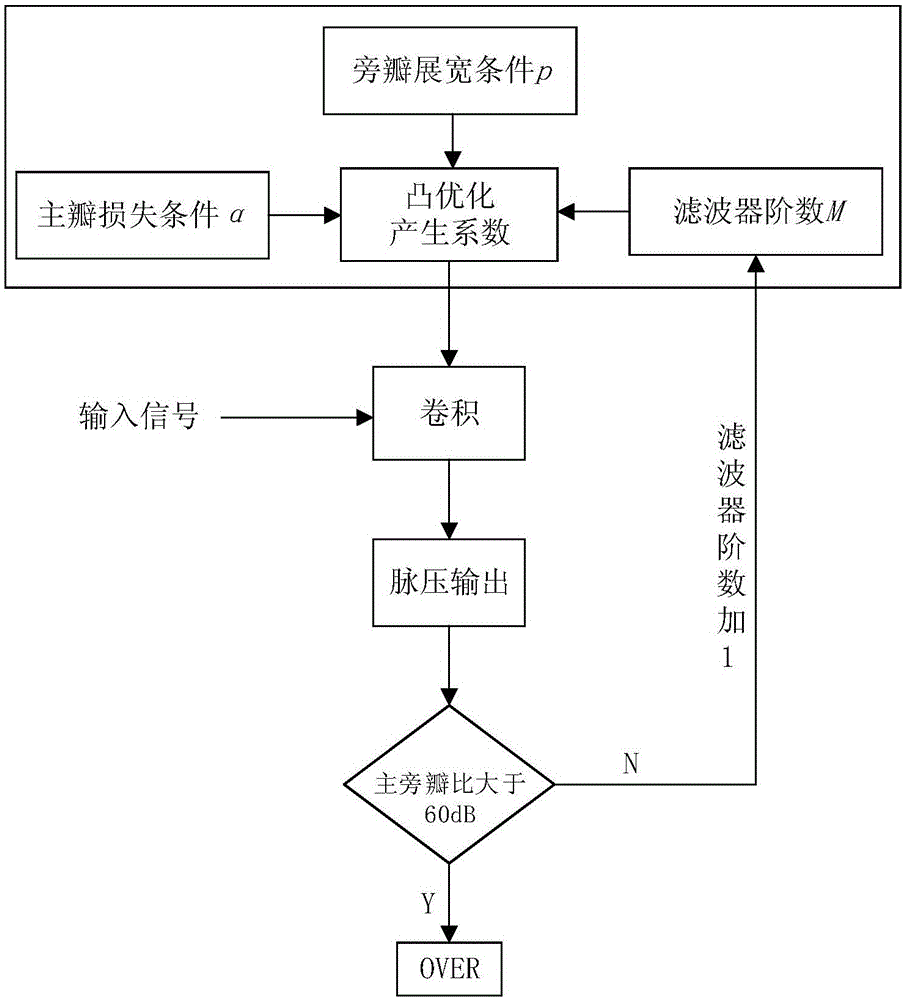
[0016] Aiming at the pulse compression and side lobe suppression of the linear frequency modulation signal, a pulse pressure filter is designed, so that the main-side lobe level ratio of the signal output after the pulse pressure filter reaches 60dB and above. How to determine the coefficients of the pulse pressure filter is the key problem to be solved in the present invention, and the present invention adopts a convex optimization (ConvexOptimization) method.

[0017] The input signal x(t) is sampled at an interval T to obtain a sampled complex sequence {x k}, written in the form of an N-dimensional vector

[0018] x=[x 0 ,x 1 ,...x N-1 ] T

[0019] Now it is necessary to design an FIR sidelobe suppression filter of order M (M≥N), so that the peak sidelobe level after filtering can meet the requirement of main-sidelobe level ratio. Let the filter coefficients be

[0020] w=[w 0 ,w 1 ,...,w M-1 ]

[0021] Then, the filtered output signal {y k}for

[0022] ...


PUM


Abstract

The invention discloses an ultra low sidelobe pulse transformer design method of a linear frequency modulation pulse signal. The method is characterized in that the linear frequency modulation signal which needs to be processed is sampled as a time interval T so as to acquire a M point sampling sequence; a sampling sequence point number is taken as a an initial point number N of a pulse pressure filter, wherein the N equals to the M; a sidelobe peak value of sampling sequence pulse pressure processing is taken as a target function and a signal to noise ratio loss and main lobe widening are taken as a limitation condition so as to establish a convex optimization model and solve, and acquire a group of pulse pressure filter coefficients; the pulse pressure filter coefficients are solved so as to acquire a corresponding pulse pressure sidelobe peak level; if the sidelobe peak level does not reach a practical application requirement, a pulse pressure filter order is N+1, the convex optimization model is rebuilt and solving is performed; if the sidelobe peak level reaches the application requirement, the pulse pressure filter coefficients, a lowest order and a peak sidelobe level after pulse pressure processing are output. By using the method in the invention, ultra low sidelobe pulse compression processing of the linear frequency modulation signal is realized; a low sidelobe level can be acquired and the order of the pulse pressure filter is flexible.

Description

technical field [0001] The invention relates to the field of radar signal processing, in particular to the pulse compression of chirp signal and its side lobe suppression processing technology, and is a design method of pulse pressure filter for chirp signal with ultra-low side lobe. Background technique [0002] Pulse compression technology can enable radar to obtain the advantages of high energy of wide pulse and high distance resolution of narrow pulse at the same time when the peak power is greatly reduced, which better solves the problem of radar peak power limitation and distance resolution. contradictions between. Therefore, the large-time-wide-bandwidth pulse compression technology has been widely used in modern radars. The linear frequency modulation (Linear Frequency Modulation, LFM) signal is the earliest studied and most widely used pulse compression signal with a large time-width-bandwidth product, and it is one of the signal waveforms often used in modern high...

Claims


Application Information

Patent Timeline
Patent Type & Authority Applications(China)
IPC IPC(8): G01S7/32
CPCG01S7/32
Inventor 施镇峰蔡雨琦孙红磊袁美娟蒋芸茹鲍昱蒙谢仁宏芮义斌郭山红李鹏
Owner NANJING UNIV OF SCI & TECH
Why Eureka
Try Eureka