Triplate-type planar array antenna

a planar array and antenna technology, applied in the structural form of individual energised antenna arrays, resonant antennas, radiating elements, etc., can solve the problems of reduced efficiency, directivity disorder, and reduced gain in frontal directions, so as to achieve the effect of low side lobe level and high degree of flexibility in beam width setting

Inactive Publication Date: 2007-07-26
HITACHI CHEM CO LTD
View PDF3 Cites 9 Cited by
  • Summary
  • Abstract
  • Description
  • Claims
  • Application Information

AI Technical Summary

Benefits of technology

[0013] Accordingly, the object of the present invention is to provide a triplate-type planar array antenna in which there is a high degree of flexibility in setting beam widths on a desired radiating plane, and a lower side lobe level can be secured even in a wider-angle direction without deteriorating the characteristics of a high-gain and high-efficiency triplate-type planar array antenna according to the prior art.

Problems solved by technology

However, as the array spacing is restricted in the neighborhood of 0.9 λo (λo is a free space wavelength) in order to achieve a high-efficiency antenna, it has been difficult as shown in FIG. 5 in an array antenna with four through eight array elements that the side lobe level of the direction of the wide angle of 60 degrees or larger is made about −20 dB or smaller.
However, there has been caused a problem that disorders are generated in the directivity, and the gain in the frontal direction is also reduced as shown by a dotted line in FIG. 6 to cause reduction in the efficiency because the phases of the transverse propagation components radiated from the adjacent slots are actually different from those of the components directly radiated from the related slots due to the effect of the transverse propagation components when the element array spacing is made smaller.
Accordingly, it has been difficult to meet the requirements for reduction in the side lobe in the direction with wider angles and for wider beam widths.

Method used


Image

  • Triplate-type planar array antenna
  • Triplate-type planar array antenna
  • Triplate-type planar array antenna

Examples


first embodiment

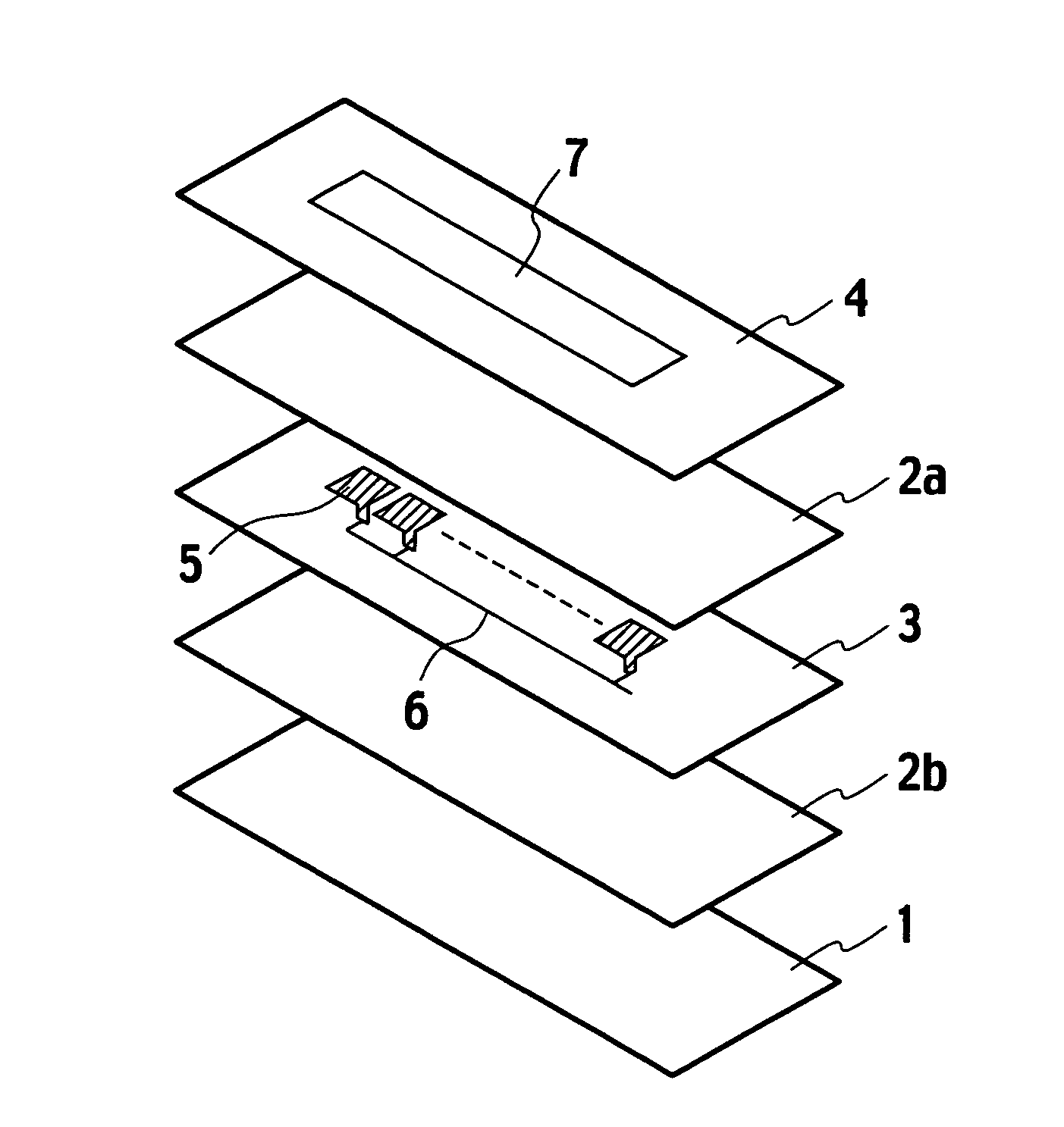
[0045]FIG. 8 is a view explaining a triplate-type planar array antenna according to a first embodiment of the invention. Hereinafter, the longitudinal direction of the slot opening 7 is called a horizontal direction, and a direction perpendicular to the horizontal direction is called a vertical direction for simplification of the explanation.

[0046] The first embodiment has a configuration in which one slot opening 7 is corresponding to m total number of the radiating elements 5 in the horizontal direction, and n number of such slot openings 7 are vertically arranged in parallel to one another as shown in FIG. 8 when the radiating elements 5 are arrayed in (vertically n and horizontally m) on the antenna circuit board 3 in a typical two-dimensional manner.

[0047] In this case, it is preferable that each array (center) spacings D1 for the plurality of slot openings 7, that is, the array spacings D1 in the vertical direction is configured at 0.85 through 0.93 times the free space wave...

second embodiment

[0055]FIG. 9 is a view explaining a configuration of triplate-type planar array antenna according to a second embodiment of the invention.

[0056] The second embodiment has a configuration in which a plurality of array antennas according to the first embodiment are provided on an antenna circuit board 3. Accordingly, the difference from the configuration of the first embodiment is that a plurality of slot openings 7 are provided on the antenna circuit board 3 in the horizontal direction.

[0057] It is also preferable in the second embodiment, as in the case of the first embodiment, that each array (center) spacing D1 for the plurality of slot openings 7, that is, the array spacings D1 in the vertical direction is configured at 0.85 through 0.93 times the free space wavelength λo for the center frequency of a frequency band in use. Moreover, it is preferable in the second embodiment, as in the case of the first embodiment, that the array spacings D2 for the plurality of radiating eleme...

third embodiment

[0063]FIG. 10 is a view explaining a configuration of triplate-type planar array antenna according to a third embodiment of the invention.

[0064] The third embodiment has a configuration in which arbitrary adjoining array antennas among a plurality of horizontal array antennas in the horizontal direction have a common slot opening 7 in the horizontal direction. In other words, the slot opening 7 extends over a plurality of the array antennas. If the number of radiating elements 5 in the horizontal direction of one array antenna is assumed to be, for example, two, and the slot opening 7 extends over two array antennas, the slot opening 7 is correspond to four radiating elements 5 in the horizontal direction.

[0065] It is also preferable in the third embodiment, as in the case of the second embodiment, that each array (center) spacing D1 for the plurality of slot openings 7, that is, the array spacings D1 in the vertical direction is configured at 0.85 through 0.93 times the free spac...


PUM


Abstract

A triplate-type planar array antenna is provided with an antenna circuit board (3) on which an antenna circuit including a plurality of radiating elements (5), which are vertically and horizontally arrayed in a two-dimensional manner, and feedlines (6) is formed; two pieces of dielectric substances (2a, 2b) between which the antenna circuit board (3) is sandwiched at the both sides; a ground conductor (1) laminated on one dielectric substance (2b); and a slot board (4) laminated on the other dielectric substance (2a). One or more slot openings (7) corresponding to the plurality of radiating elements (5) with a linear arrangement are formed on the slot board (4).

Description

TECHNICAL FIELD [0001] The present invention relates to a triplate-type planar array antenna used for transmitting and receiving with a millimeter-wave band, and especially, to a triplate-type planar array antenna which can improve beam widths and a level of wide-angle side lobe. BACKGROUND ART [0002] High gain and low side lobe characteristics are important for the planar array antenna used for an on-vehicle radar and a high-speed communication through a millimeter-wave band. There have been already well-known a planar array antenna that is a high gain planar array antenna which can be applied to the above uses, and by which reduction of a feedline loss and control of an unnecessary radiation of feedline can be realized (refer to, for example, Japanese Patent Application Laid-Open No. 4-82405). [0003] Hereinafter, the outline of such a planar array antenna will be given, based on FIGS. 1 through 6. [0004]FIG. 1 is an exploded perspective view showing an outline configuration of suc...

Claims


Application Information

Patent Timeline
Patent Type & Authority Applications(United States)
IPC IPC(8): H01Q1/38H01Q21/06H01Q13/16
CPCH01Q21/065H01Q21/064
Inventor MIZUGAKI, HISAYOSHIOOTA, MASAHIKO
Owner HITACHI CHEM CO LTD
Why Eureka
Try Eureka