Method for designing slow wave structure of CTS antenna and VICTS antenna

A slow-wave structure and design method technology, applied in the field of satellite communication antennas, can solve problems such as difficult theoretical analysis of antennas, complex structure design, array optimization, etc.

Active Publication Date: 2018-05-25
PLA STRATEGIC SUPPORT FORCE INFORMATION ENG UNIV PLA SSF IEU +1
View PDF4 Cites 5 Cited by
  • Summary
  • Abstract
  • Description
  • Claims
  • Application Information

AI Technical Summary

Problems solved by technology

However, the theoretical analysis of the CTS / VICTS antenna based on the nonlinear rectangular comb slow-wave structure is difficult, and the structural design is complicated. There is no special literature research at present.
Therefore, this patent proposes a CTS / VICTS antenna slow-wave structure design method for this problem to solve the array optimization problem in CTS / VICTS antenna design

Method used


Image

  • Method for designing slow wave structure of CTS antenna and VICTS antenna
  • Method for designing slow wave structure of CTS antenna and VICTS antenna
  • Method for designing slow wave structure of CTS antenna and VICTS antenna

Examples


Embodiment Construction

[0041]In order to make the purpose, technical solutions and advantages of the embodiments of the present invention clearer, the technical solutions in the embodiments of the present invention will be clearly and completely described below in conjunction with the drawings in the embodiments of the present invention. Obviously, the described embodiments It is a part of embodiments of the present invention, but not all embodiments. Based on the embodiments of the present invention, all embodiments obtained by persons of ordinary skill in the art without making creative efforts belong to the protection scope of the present invention.

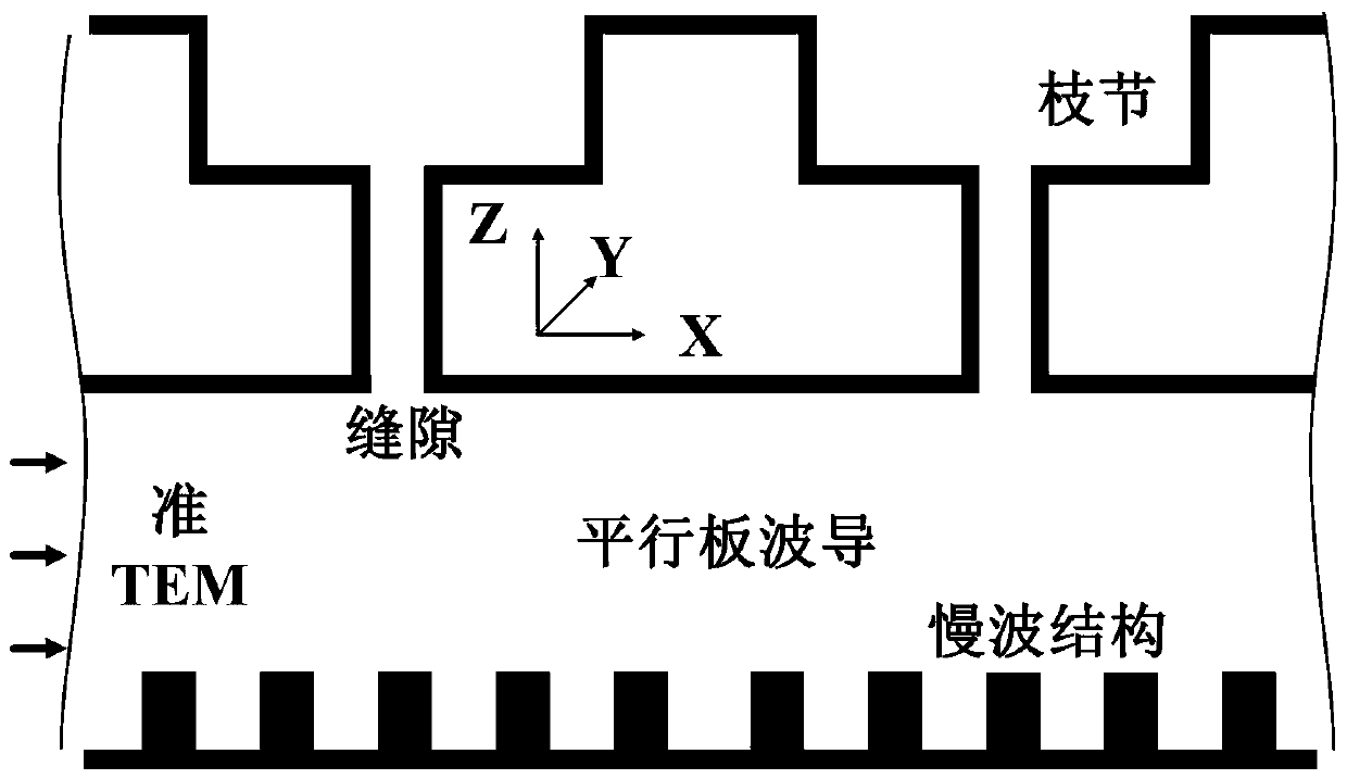
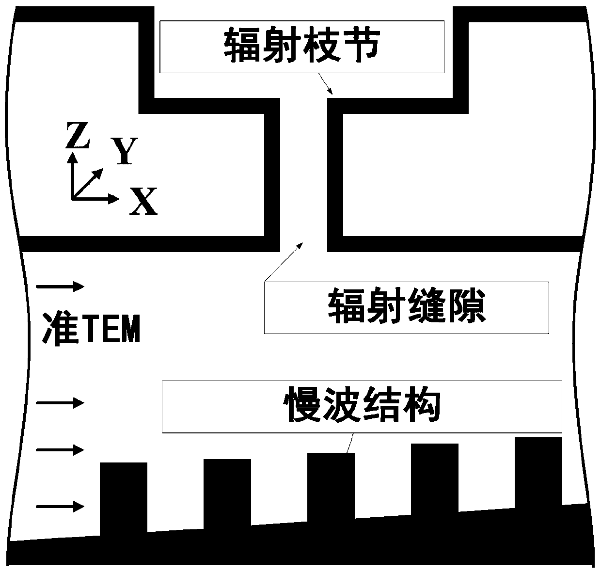
[0042] First, the basic structure of the antenna is briefly introduced: upper and lower metal parallel plates, radiation slots, matching stubs, slow wave structure and feed source structure. A gap is cut on the upper parallel plate, and a matching branch is loaded on the gap, and the gap and the branch are collectively called a transverse radial bra...


PUM


Abstract

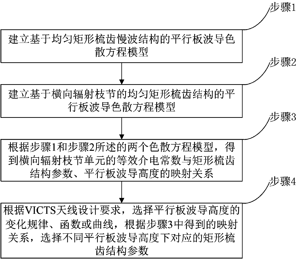
The invention belongs to the technical field of satellite communication antennas, and particularly relates to a method for designing a slow wave structure of a CTS antenna and a VICTS antenna. Firstly, a parallel plate waveguide dispersion equation model based on a uniform rectangular comb tooth slow wave structure is established to establish a parallel-plate waveguide dispersion equation model with a uniform rectangular comb tooth structure based on horizontal radiation branching; according to the two dispersion equation models, obtaining a mapping relationship between an effective dielectricconstant of a horizontal radiation branching unit and rectangular comb tooth structure parameters and the height of a parallel plate waveguide; finally according to the VICTS antenna design requirements, choosing a variation rule, function or curve of the height of the parallel plate waveguide, and according to the obtained mapping relationship, selecting the corresponding rectangular comb toothstructure parameters under different parallel plate waveguide heights. According to the method for designing the slow wave structure of the CTS antenna and the VICTS antenna, by the nonlinear design on rectangular comb teeth which are of the slow wave structure in the VICTS antenna, while array optimization is achieved, it is ensured that parameters such as the gain of the antenna and the standing-wave ratio do not deteriorate or even are improved.

Description

technical field [0001] The invention belongs to the technical field of satellite communication antennas, in particular to a slow-wave structure design method for a CTS antenna and a VICTS antenna. Background technique [0002] The VICTS (Variable Inclination Continuous Transverse Stub) array antenna is developed from the CTS (Continuous Transverse Stub) array antenna. The typical parallel-plate waveguide CTS antenna is a frequency-swept leaky-wave antenna that combines the lateral radiation stub of the CTS antenna with the The relative rotation of the feeding structure can realize the VICTS antenna with full spatial beam scanning capability. In the design process of the VICTS antenna, in order to realize the large-angle scanning of the antenna and suppress the grating lobes, a slow-wave structure design needs to be added to the CTS array. Generally, a rectangular comb-shaped metal structure is used. This rectangular comb-shaped structure is excited by periodic disturbances. ...

Claims


Application Information

Patent Timeline
Patent Type & Authority Applications(China)
IPC IPC(8): G06F17/50
CPCG06F30/20
Inventor 雷雪高峻陈国虎张毅徐志坚李天鹏刘铮胡浩明魏进进张刚
Owner PLA STRATEGIC SUPPORT FORCE INFORMATION ENG UNIV PLA SSF IEU
Why Eureka
Try Eureka