Substrate integrated ridge waveguide slot array broadband leaky-wave antenna

A substrate-integrated waveguide and slot array technology, applied in slot antennas, antennas, antenna arrays, etc., can solve the problems of low side lobes, inability to meet high gain, etc., and achieve high gain, easy processing and integration, and the effect of expanding the working frequency band

Inactive Publication Date: 2017-01-04
SICHUAN ZHONGCE MICROGRID TECH CO LTD
View PDF1 Cites 8 Cited by
  • Summary
  • Abstract
  • Description
  • Claims
  • Application Information

AI Technical Summary

Problems solved by technology

At present, the working bandwidth of the existing frequency-swept leaky-wave antennas only reaches about 5%, and the 3dB beamwidth of the H-plane is equal to or greater than 50°, and cannot meet the requirements of high gain, low sidelobe, simple structure, and easy integration. Require

Method used


Image

  • Substrate integrated ridge waveguide slot array broadband leaky-wave antenna
  • Substrate integrated ridge waveguide slot array broadband leaky-wave antenna
  • Substrate integrated ridge waveguide slot array broadband leaky-wave antenna

Examples


Embodiment 1

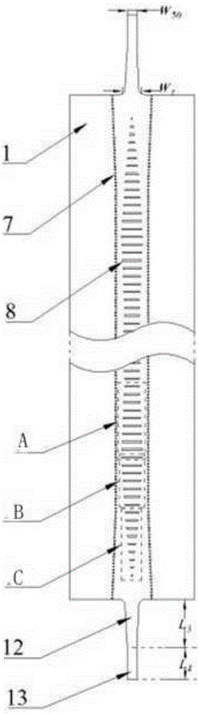
[0048] Such as Figure 1 to Figure 9 A substrate-integrated ridge waveguide slot array broadband leaky-wave antenna is shown, which has a symmetrical structure with respect to the H plane, including a substrate-integrated waveguide and a ridge metal layer 3, and the substrate-integrated waveguide includes a lower metal layer 5 and a lower dielectric plate 4. The upper dielectric plate 2 and the upper metal layer 1;

[0049] In this embodiment, the lower metal layer 5, the lower dielectric plate 4, the ridge metal layer 3, the upper dielectric plate 2 and the upper metal layer 1 are stacked in sequence;

[0050] A row of side vias 6 are respectively provided on both sides of the ridge metal layer 3 in this embodiment, and the side vias 6 pass through the lower metal layer 5 , the lower dielectric plate 4 , the upper dielectric plate 2 and the upper metal layer 1 in sequence;

[0051] In this embodiment, a row of middle vias 7 is provided on the centerline of the lengthwise dir...

Embodiment 2

[0054] On the basis of the structure of Embodiment 1, the ridge metal layer 3 is strip-shaped, and its width is greater than the diameter of the middle via hole 7 , and the length of the ridge metal layer 3 is greater than the length of the substrate integrated waveguide.

[0055] The distance between two adjacent middle via holes 7 is 0.03λ to 0.05λ, and λ is the center frequency wavelength;

[0056] The diameter of the side via holes 6 in this embodiment is 0.017λ˜0.027λ, and the distance between two adjacent side via holes 6 in each row is less than or equal to the diameter of the side via holes 6;

[0057] In this embodiment, the diameters of the side via hole 6 and the middle via hole 7 are equal, and the height of the middle via hole 7 is half of the height of the side via hole 6 .

[0058] The ridge metal layer 3 above the metal spine is designed to further expand the bandwidth based on the ridge waveguide. The metal strip must have a certain lateral width in order to ...

Embodiment 3

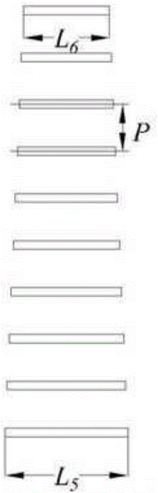
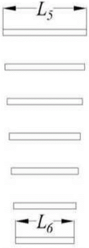
[0061] On the basis of the above embodiments, a leaky wave structure is also included, and the leaky wave structure includes a row of transverse grooves 8 arranged on the upper metal layer 1 .

[0062] The widths of the transverse grooves 8 are equal, and the intervals between two adjacent transverse grooves are equal.

[0063] The lengths of the transverse grooves 8 are periodically distributed, and the maximum length of the transverse grooves 8 is 0.2λ˜0.25λ, and the minimum length is 0.15λ˜0.2λ in each length variation period.

[0064] The most important part in the structure of the leaky wave antenna is the leaky waveguide with a certain length. In the present invention, a series of horizontal grooves are opened for the upper metal layer 1 to integrate the ridge waveguide. The propagation characteristics of the waveguide leaky mode in the wave propagation direction Determined by the phase constant β and the leakage constant α. In order to couple more electromagnetic waves...


PUM


Abstract

The invention discloses a substrate integrated ridge waveguide slot array broadband leaky-wave antenna which is of a symmetrical structure about an H surface. The substrate integrated ridge waveguide slot array broadband leaky-wave antenna comprises a substrate integrated waveguide and a ridge metal layer, wherein the substrate integrated waveguide comprises a lower metal layer, a lower dielectric plate, an upper dielectric plate and an upper metal layer; the lower metal layer, the lower dielectric plate, the ridge metal layer, the upper dielectric plate and the upper metal layer are overlapped in sequence; a row of side via holes is formed in each side of the ridge metal layer, and the side via holes pass through the lower metal layer, the lower dielectric plate, the upper dielectric plate and the upper metal layer in sequence; a row of middle via holes is further formed in the center line of the ridge metal layer in the length direction, and the middle via holes pass through the lower metal layer, the lower dielectric plate and the ridge metal layer (3) in sequence; the antenna can realize frequency scanning of 28 degrees to 84 degrees on the H surface, and the impedance bandwidth can reach 38%; and meanwhile, the antenna has the prominent advantages of being high in gain, low in minor lobe level, easy to machine and integrate and the like.

Description

technical field [0001] The invention relates to the field of antennas, in particular to a substrate integrated ridge waveguide slot array broadband leaky wave antenna. Background technique [0002] As a device for radiating or receiving radio waves, an antenna is one of the most basic components of a radio communication system. The performance of the antenna directly restricts the communication quality of the radio communication system. The waveguide slot antenna is composed of slots opened on the waveguide wall. In order to enhance the directivity of the waveguide slot antenna, one or more slots of the same size or different sizes are usually opened on the same side wall of the waveguide according to certain rules. array. The waveguide slot array antenna has narrow main lobe beam, low side lobe level, low cross polarization level, and easy to achieve high gain, so it is a hot spot in the research of array antenna. [0003] The waveguide slot array antenna made of the tra...

Claims


Application Information

Patent Timeline
Patent Type & Authority Applications(China)
IPC IPC(8): H01Q13/08H01Q13/10H01Q1/38H01Q21/00
CPCH01Q13/08H01Q1/38H01Q13/085H01Q13/106H01Q21/00
Inventor 董宇亮甘雨辰邓建华
Owner SICHUAN ZHONGCE MICROGRID TECH CO LTD
Why Eureka
Try Eureka