Method, device and system for suppressing circulation between high-power pwm rectifier power supply modules
A rectifying power supply and circulating current suppression technology, which is applied in the field of power system, can solve the problems of inconsistent switching time of multiple rectifying power supply modules, affecting the safety of distribution network, etc., and achieve the effect of balancing load, improving safety and stability, and suppressing circulating current
- Summary
- Abstract
- Description
- Claims
- Application Information
AI Technical Summary
Problems solved by technology
Method used
Image
Examples
Embodiment 1
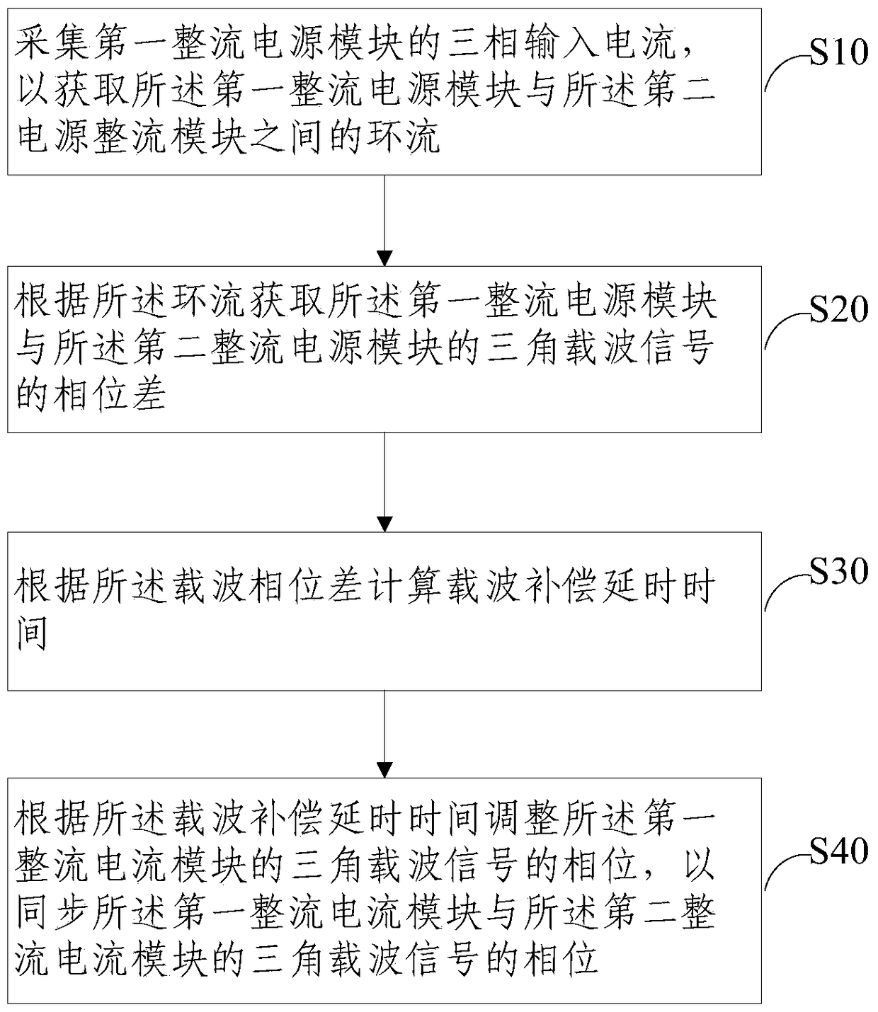
[0032] Such as figure 1 As shown, the embodiment of the present invention provides a method for suppressing circulation between high-power PWM rectified power supply modules. The high-power PWM rectified power supply includes a first rectified power supply module and a second rectified power supply module. The method includes:
[0033] S10. Collect the three-phase input current of the first rectifying power module, so as to obtain the circulating current between the first rectifying power module and the second rectifying power module;
[0034] S20. Obtain the phase difference of the triangular carrier signal of the first rectifying power module and the second rectifying power module according to the circulating current;
[0035] S30. Calculate the carrier compensation delay time according to the carrier phase difference;
[0036] S40. Adjust the phase of the triangular carrier signal of the first rectified current module according to the carrier compensation delay time, so as...
Embodiment 2
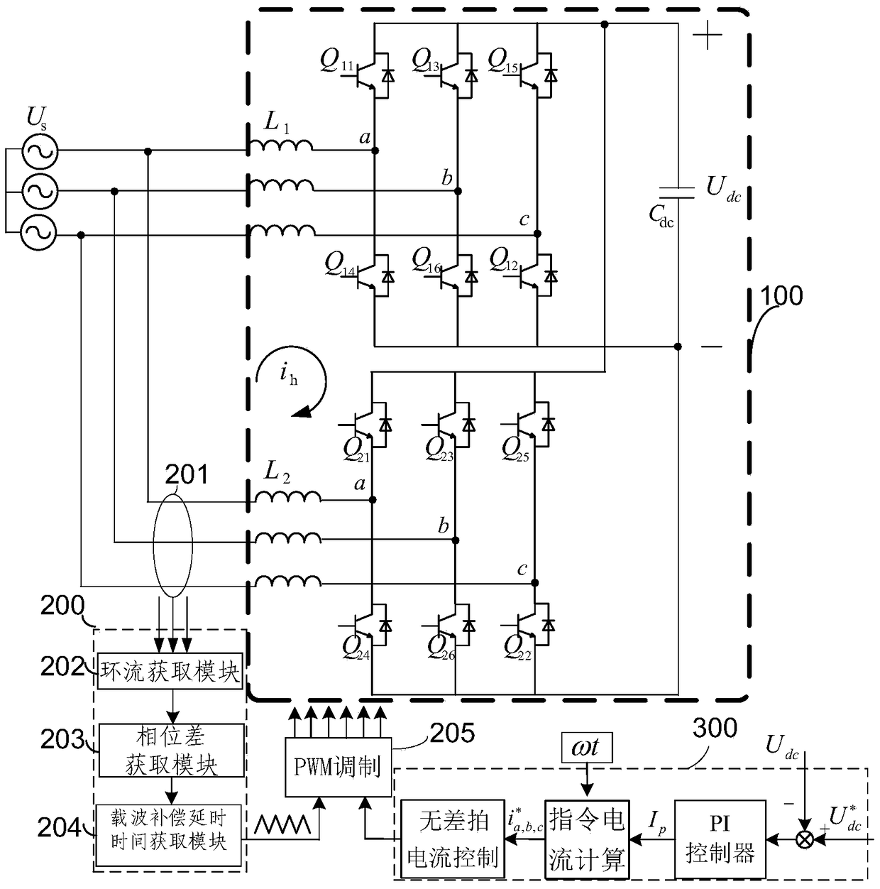
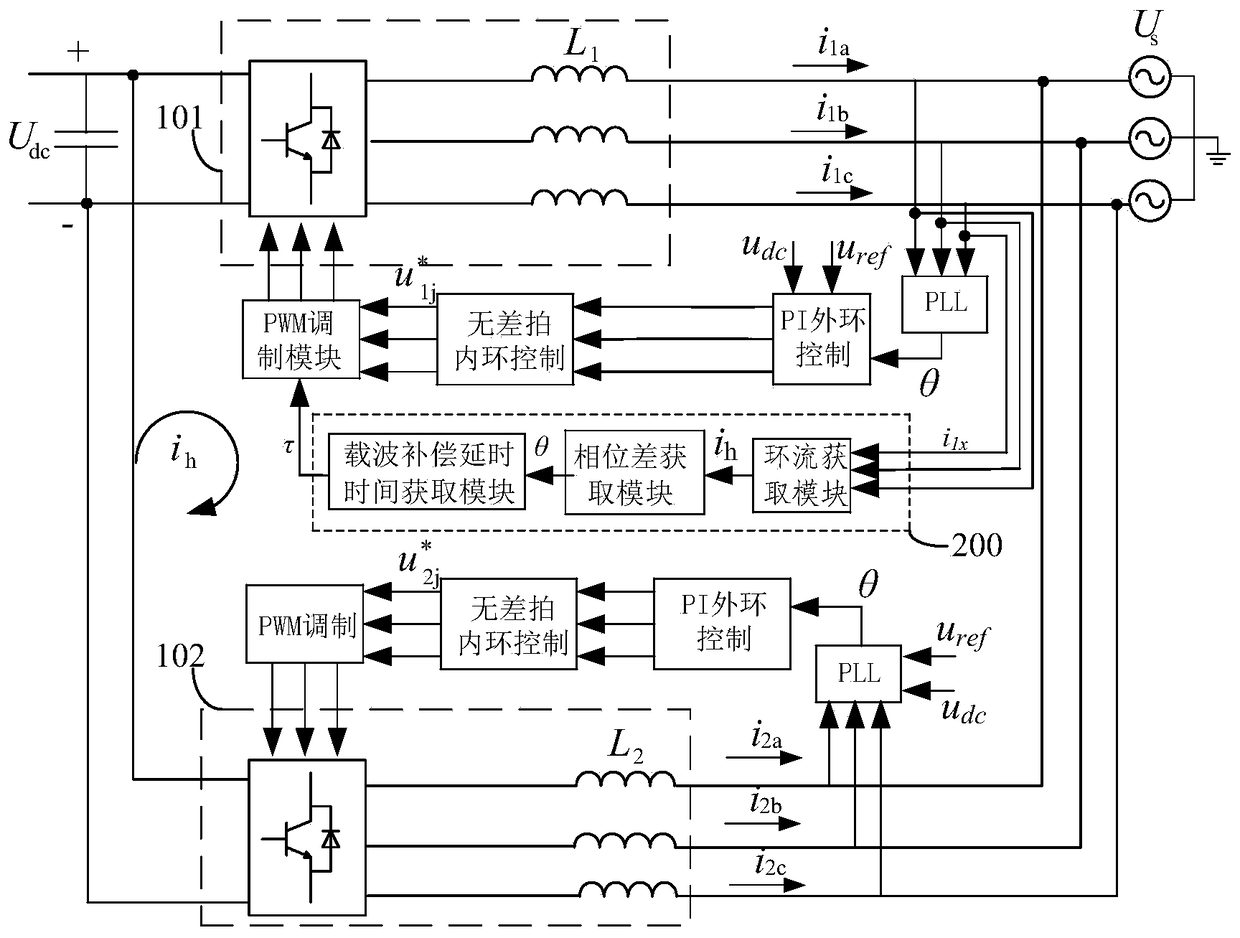
[0056] Such as figure 2 and image 3 As shown, the high-power PWM rectified power supply provided by the embodiment of the present invention includes: a rectified power supply main circuit 100 composed of a first rectified power supply module 101 and a second rectified power supply module 102 connected in parallel, a circulating current suppression device 200 and a voltage and current control module 300 .
[0057] Among them, the circulation suppression device 200 provided by the embodiment of the present invention, such as figure 2 and image 3 shown, including:
[0058] The circulating current acquisition module 202 is configured to collect the three-phase input current of the first rectified power supply module, so as to obtain the circulating current between the first rectified power supply module and the second rectified power supply module; The three-phase input current i of the second rectified power module 2a i 2b i 2c The zero-sequence current of the second re...
Embodiment 3
[0066] An embodiment of the present invention also provides a circulation suppression system between high-power PWM rectification power supply modules, including the circulation suppression device described above. Based on the same purpose of the invention, the same technical problem is solved, and the same technical effect is achieved, the embodiments of the present invention will not be repeated one by one.
[0067] To sum up, the embodiment of the present invention provides a method, device and system for suppressing circulating current between high-power PWM rectifying power modules. The circulating current is obtained by collecting the input current of the rectifying power module, and the carrier wave of the two rectifying power modules is obtained according to the circulating current. The phase difference between the two rectifier power modules can be obtained to obtain the carrier compensation delay time. According to the carrier delay time, the phase of the carrier wave...
PUM
 Abstract
Description
Claims
Application Information
 - R&D
- Intellectual Property
- Life Sciences
- Materials
- Tech Scout
- Unparalleled Data Quality
- Higher Quality Content
- 60% Fewer Hallucinations
Browse by: Latest US Patents, China's latest patents, Technical Efficacy Thesaurus, Application Domain, Technology Topic, Popular Technical Reports.
© 2025 PatSnap. All rights reserved.Legal|Privacy policy|Modern Slavery Act Transparency Statement|Sitemap|About US| Contact US: help@patsnap.com


