Evacuation of liquid from acoustic space

An acoustic, liquid technology used in the field of emptying acoustic spaces to solve problems such as preventing the correct operation of acoustic modules

Active Publication Date: 2015-11-11
APPLE INC
View PDF4 Cites 30 Cited by
  • Summary
  • Abstract
  • Description
  • Claims
  • Application Information

AI Technical Summary

Problems solved by technology

Even when preventing damage from such liquids, this obstruc

Method used


Image

  • Evacuation of liquid from acoustic space
  • Evacuation of liquid from acoustic space
  • Evacuation of liquid from acoustic space

Examples


Embodiment Construction

[0022] The following description includes example systems, methods, and computer program products that embody various elements of the disclosure. It should be understood, however, that the described disclosure may be practiced in various forms other than those described herein.

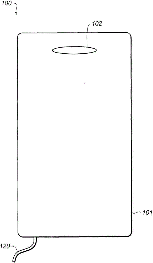
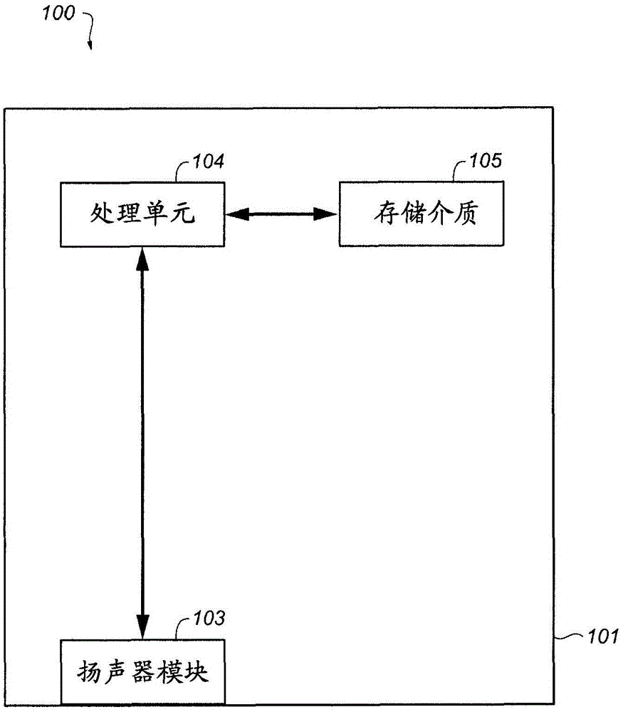
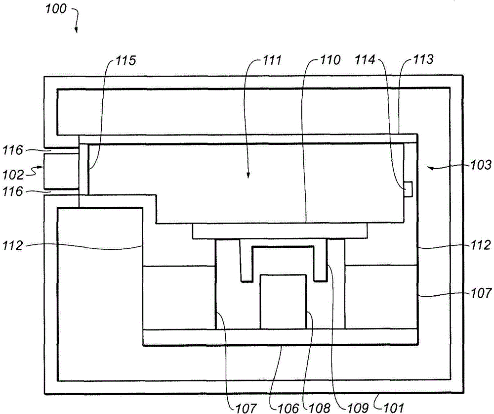
[0023] The present disclosure discloses systems, methods and devices for evacuating liquid from an acoustic space. An acoustic module, such as a microphone or a speaker module, may include an acoustic membrane vibrating to generate sound waves and an acoustic cavity through which sound waves generated by the acoustic membrane propagate. A liquid removal mechanism may remove liquid from the acoustic cavity.

[0024] In various implementations, the liquid removal mechanism can include an acoustic membrane that can generate one or more acoustic signals to force the liquid out of the acoustic cavity. Such acoustic signals may be outside the human audible acoustic range which may be between 20 Hz and 200...


PUM


Abstract

An acoustic module, such as a microphone or speaker module, includes an acoustic membrane that vibrates to produce acoustic waves and an acoustic cavity through which acoustic waves produced by the membrane travel. A liquid removal mechanism removes liquid from the acoustic cavity. Such a liquid removal mechanism may include the acoustic membrane, heating elements, hydrophobic and/or hydrophilic surfaces, and so on. In some cases, the liquid removal mechanism may remove liquid from the acoustic cavity upon connection of the acoustic module and/or an associated electronic device to an external power source.

Description

[0001] Cross References to Related Applications [0002] This application claims the benefit under 35 U.S.C. §119(e) of U.S. Provisional Patent Application No. 61 / 986,302, filed April 30, 2014, entitled "Evacuation of Liquid from Acoustic Space," which is hereby incorporated by reference in its entirety for It seems to be fully disclosed in this article. technical field [0003] The present disclosure relates generally to acoustic modules, and more particularly to the evacuation of liquid from an acoustic space of an acoustic module. Background technique [0004] Many acoustic modules, such as microphones or speakers, utilize an acoustic membrane to generate or receive sound. For example, the acoustic membrane of a speaker module can vibrate to generate sound waves that propagate into the external environment. However, since the sound waves generated by such an acoustic membrane must be able to propagate to the external environment, liquids from the external environment ma...

Claims


Application Information

Patent Timeline
IPC IPC(8): H04R1/02
CPCH04R1/44H04R1/023H04R3/007H04R7/08H04R7/122H04R2499/11H04R1/025H04R1/24H04R9/02H04R2209/00H04R29/001H04R2499/15
Inventor J·A·利珀特N·T·维特C·维尔克R·T·埃曼
Owner APPLE INC
Why Eureka
Try Eureka