Transmission system of portable mini tiller

A technology of transmission system and micro-tiller, which is applied in the field of transmission mechanism of micro-tiller, can solve the problems of unfavorable miniaturization, high production cost, high precision requirements, etc., and achieve the effect of less parts, low cost and stable transmission

Inactive Publication Date: 2015-11-18
CHONGQING JIAMU MACHINERY
View PDF6 Cites 6 Cited by
  • Summary
  • Abstract
  • Description
  • Claims
  • Application Information

AI Technical Summary

Benefits of technology

This patented technology simplifies the design of an engine by allowing its components to fit within one space instead of being placed next to each other or inside another larger housing. It also reduces manufacturing expenses while maintaining efficient performance levels compared to existing designs. Additionally, this new arrangement allows for more flexibility in terms of how various functions may operate without requiring multiple large housings. Overall, these technical improvements improve the overall functionality and reliability of the motorized equipment used in gardeners.

Problems solved by technology

This patented technical problem addressed in this patents relates to improving the design of an electric troweling system that uses less expensive engine technology compared to traditional methods such as cowspeckering.

Method used


Image

  • Transmission system of portable mini tiller
  • Transmission system of portable mini tiller

Examples


Embodiment Construction

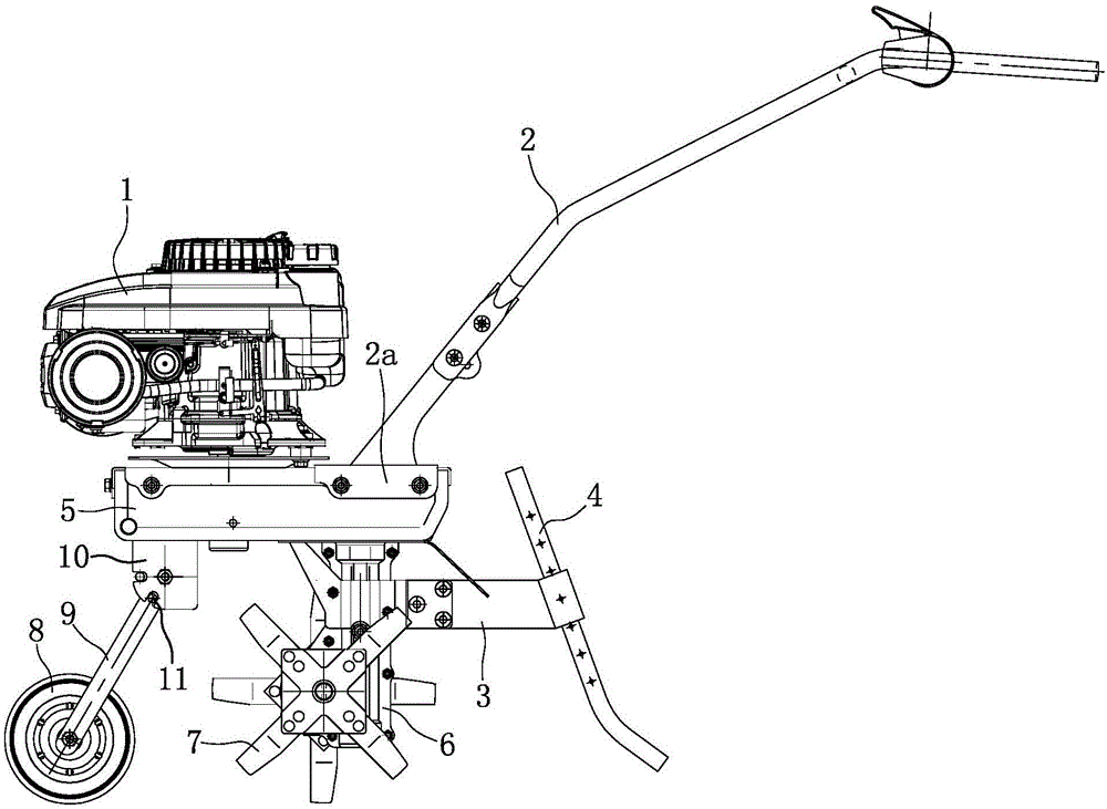
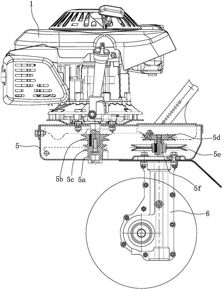
[0013] Below in conjunction with accompanying drawing and embodiment the present invention will be further described:

[0014] Such as figure 1 , figure 2 As shown, engine 1 is installed at the front end of main transmission case 5 top, and this engine 1 is the vertical axis engine that output shaft is vertically downward, and the output shaft of engine 1 stretches in the main transmission case 5, and is connected with driving wheel shaft 5a, The lower end of the driving wheel shaft 5a protrudes downwards from the bottom surface of the main transmission case 5, and the lower end of the driving wheel shaft 5a is integrally formed with end teeth evenly distributed around the circumference. A high-speed driving wheel 5b and a low-speed driving wheel 5c are integrally formed on the driving wheel shaft 5a, and the high-speed driving wheel 5b is located above the low-speed driving wheel 5c. The high-speed driving wheel 5b can be connected with the high-speed driven wheel 5d throu...


PUM


Abstract

The invention discloses a transmission system of a portable mini tiller. An output shaft of an engine (1) stretches into a main transmission case (5) and is connected with a driving wheel shaft (5a); the lower end of the driving wheel shaft (5a) stretches downwards out of the bottom surface of the main transmission case (5); end surface teeth are uniformly distributed at the periphery of the lower end of the driving wheel shaft (5a) in an integrated manner; a high-speed driving wheel (5b) and a low-speed driving wheel (5c) are arranged on the driving wheel shaft (5a); a high-speed driven wheel (5d) and a low-speed driven wheel (5e) are respectively arranged on a driven wheel shaft (5f); the lower end of the driven wheel (5f) is connected with the input end of a worm-gear transmission case (6); the worm-gear transmission case (6) is positioned under the rear end of the main transmission case(5); tilling blades (7) or walling wheels are mounted on the output shaft of the worm-gear transmission case (6). The portable transmission system disclosed by the invention has a high-speed gear and a low-speed gear, and adopts a belt to perform transmission, so that the transmission is stable and reliable; therefore, the portable transmission system is wide in application range.

Description


Claims


Application Information

Patent Timeline
Owner CHONGQING JIAMU MACHINERY
Why Eureka
Try Eureka