Anti-winding device of tea garden tillage implement
An anti-winding and cultivating machine technology, which is applied in the fields of tillage machines, agricultural machinery and implements, etc., to achieve the effect of simple structure and anti-winding
- Summary
- Abstract
- Description
- Claims
- Application Information
AI Technical Summary
Problems solved by technology
Method used
Image

Examples
Embodiment Construction
[0013] The present invention will be described in further detail below by means of specific embodiments:
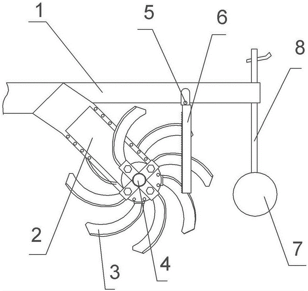
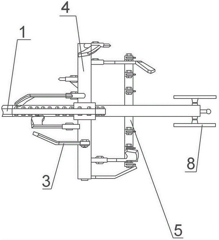
[0014] The reference signs in the accompanying drawings include: 1-frame; 2-gearbox; 3-rotary tiller; 4-rotary tiller shaft; 5-static knife shaft; 6-stationary blade; ; 8 - Depth gauge rod.
[0015] The embodiment is basically as attached figure 1 Shown:
[0016] An anti-winding device for a tea garden cultivator includes a frame, a power system, a transmission system and a rotary tiller shaft; the power system includes a diesel engine, and the traditional system includes a gearbox 2. The diesel engine, the gearbox 2 and the rotary tiller shaft 4 are all arranged on the frame 1, the diesel engine is connected with the gearbox 3, and the gearbox 3 is connected with the rotary tiller shaft 4. Such as figure 2 As shown, eight rotary tiller blades 3 are connected by bolts on the rotary blade shaft 4; the static blade shaft 5 is connected by bolts on the front end of the ...
PUM
 Abstract
Description
Claims
Application Information
PatSnap Eureka turns technology decisions into work you can execute. Powered by our Innovation Knowledge Graph, it runs expert workflows across engineering, life sciences, materials and intellectual property. Get your review-ready output in minutes.


