Countercurrent extraction apparatus

A technology of countercurrent extraction and extraction tube, applied in the direction of solid solvent extraction, etc., can solve the problems of poor uniformity, lower equipment cost performance, limit extraction rate, etc., and achieve the effect of exerting efficiency and improving cost performance

Active Publication Date: 2015-11-18
JINING SINOBEST BIOLOGICAL MACHINERY
View PDF4 Cites 6 Cited by
  • Summary
  • Abstract
  • Description
  • Claims
  • Application Information

AI Technical Summary

Problems solved by technology

In this case, the propeller only plays the role of propulsion, and the material will not disperse if it is not tossed and stirred by external force, and the uniformity of extraction is poor, which greatly limits the improvement of extraction rate and is not conducive to the improvement of equipment performance. play, reducing the cost performance of the equipment
To meet the requirement of high extraction rate, it is necessary to increase the length of the extraction tube, which increases the floor space and investment of the equipment; the second is that when the extraction tube is circular, when the total volume of the material in the extraction tube exceeds the extraction tube When the effective total volume is 40%, the material will rotate with the rotation to cause the material to rotate in situ. Because it is a continuous belt blade, the material will be tightly piled up on the side of the extraction tube, forming a shaft-holding effect, which will cause blockage, which also greatly limits Improve the performance of the extraction tube and reduce the cost performance of the equipment

Method used


Image

  • Countercurrent extraction apparatus
  • Countercurrent extraction apparatus
  • Countercurrent extraction apparatus

Examples


Embodiment 1

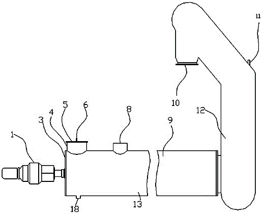
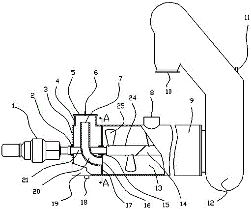
[0024] Embodiment 1: as Figure 1-2 Shown, a kind of countercurrent extracting device, it comprises extraction tube 9, is provided with propeller 14 in extraction tube 9, and propeller 14 is made of shaft 24 and vane 25, and described vane 25 is sheet shape, and described vane 25 is on shaft The surfaces of 24 are arranged at intervals along the axial direction and arranged in a spiral shape. Such as Figure 6 and 7 As shown, the tip of the blade 25 is wide, the root of the blade is narrow, the root of the blade is directly connected to the shaft 24, and the center line of the blade 25 is perpendicular to the center line of the shaft 24; Figure 12-14 As shown, the angle between the projection lines of the centerlines of the two adjacent blades 25 on the section perpendicular to the axis 24 is 60-120 degrees; as Figure 18As shown, the installation angle of the tip of the blade 25 is 5-80 degrees, and the connection line between the root of the blade and the surface of the ...

Embodiment 2

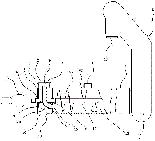
[0028] Embodiment 2: The similarities between this embodiment and Embodiment 1 will not be repeated, and the difference is that image 3 As shown, the blades of the propeller 14 between the baffle plate 17 and the feed inlet 8 can be continuous belt blades 22 .


PUM


Abstract

A countercurrent extraction apparatus comprises an extraction tube; a propeller is disposed within the extraction tube; the propeller comprises a shaft and blades. The apparatus is characterized in that the blades are sheet-shaped, and the blades are arranged at interval on the surface of the shaft along the axial direction and in spiral arrangement. The sheet-shaped blades arranged spaced axially and spirally play the role of advancing the materials; the materials under the effect of such blades churn and spread out, so as to play a role in stirring; the materials churn from one side to the other side with the rotation of the propeller; although part of the materials rotate with the blades in place, the materials do not accumulate to one side at the same time because of spaced blades; continuous closely packed body can not be formed, and journal sticking effect can be avoided, so that blockage does not form in the extraction tube. Several tests prove that even if the total volume of the materials is greater than 80% of the total volume of the extraction tube, blockage does not appear, so that the efficiency of the extraction tube plays to the maximum, and the cost performance has been significantly improved.

Description

technical field [0001] This program involves a device that uses liquid medium to extract solid materials (hereinafter referred to as materials), especially the material and liquid medium flow in the opposite direction in the extraction tube, and a spiral arrangement of sheet-shaped blades is built in the extraction tube. The thruster propels the countercurrent extraction device for material delivery. Background technique [0002] In the prior art, the technical solution closest to this application is the continuous countercurrent extraction machine in use. This continuous countercurrent extraction machine is composed of an extraction tube, and the inside of the extraction tube is equipped with a screw propeller. The screw propeller is a continuous belt. Type blades are arranged in a spiral shape along the axial direction. Under the action of the screw propeller, the material is transported from one end of the extraction pipe to the other end, and the extraction solvent flows...

Claims


Application Information

Patent Timeline
Patent Type & Authority Applications(China)
IPC IPC(8): B01D11/02
Inventor 白中明
Owner JINING SINOBEST BIOLOGICAL MACHINERY
Why Eureka
Try Eureka