Clamp for vibration testing of square plate simply supported on four sides
A vibration test, four-sided simply supported technology, applied in the direction of manufacturing tools, workpiece clamping devices, etc., can solve the problem that the four-sided simply supported constraints of the square plate cannot be effectively realized, the connection between the square plate and the fixture is easy to loosen, the fixture structure or design parameters Unreasonable and other problems, to achieve the effect of high rigidity and mass, compact structure and enhanced rigidity
- Summary
- Abstract
- Description
- Claims
- Application Information
AI Technical Summary
Problems solved by technology
Method used
Image

Examples
Embodiment 1
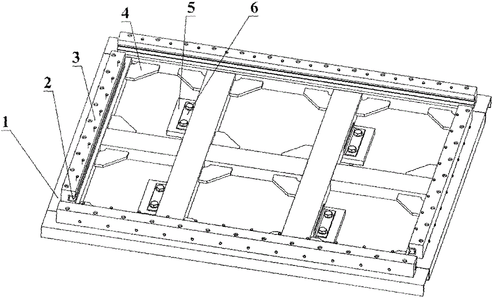
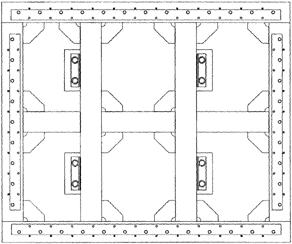
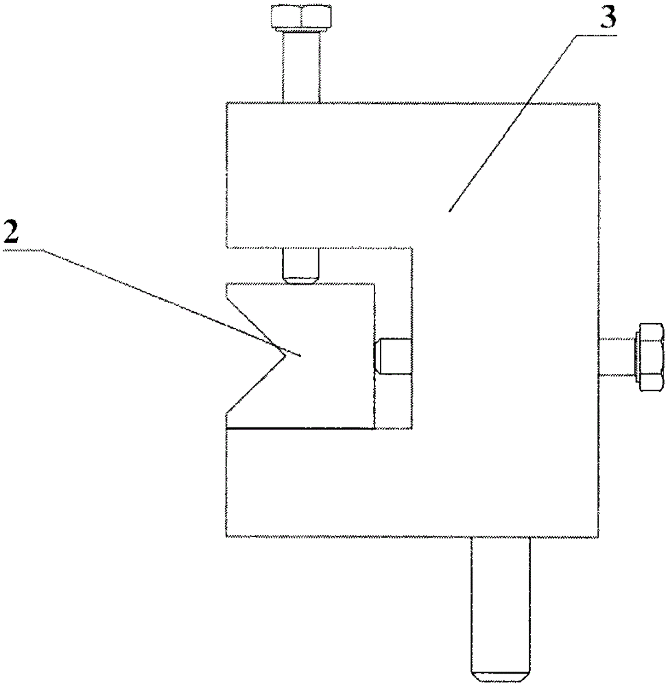
[0036] Such as figure 1 As shown, a fixture for vibration testing of a four-sided simply supported square plate, the fixture includes a base 1, an adjustable locking member and a bead 2, the base 1 includes oppositely arranged front and rear support channels and left, The right support channel steel, the front and rear support channel steels are provided with transverse ribs equidistant from the front and rear support channel steels, and two longitudinal ribs are arranged vertically and equidistantly on the transverse ribs, the front and rear support channel steels and the left 1. On the upper surface of the right support channel steel, two sets of adjustable locking strips 3 of equal length are respectively arranged in parallel. The inner side of the adjustable locking strip 3 is provided with a groove of equal height, and a bead 2 is arranged in the groove. The side of the channel steel of the base 1 Anti-corrosion paint is applied after the rust removal treatment, and the s...
PUM
 Abstract
Description
Claims
Application Information
 - R&D
- Intellectual Property
- Life Sciences
- Materials
- Tech Scout
- Unparalleled Data Quality
- Higher Quality Content
- 60% Fewer Hallucinations
Browse by: Latest US Patents, China's latest patents, Technical Efficacy Thesaurus, Application Domain, Technology Topic, Popular Technical Reports.
© 2025 PatSnap. All rights reserved.Legal|Privacy policy|Modern Slavery Act Transparency Statement|Sitemap|About US| Contact US: help@patsnap.com