

Optimization design method of impeller rotating subsystem
A technology of optimal design and rotor, applied in design optimization/simulation, computer-aided design, calculation, etc., can solve the problem of ignoring the relationship between subsystems, and achieve the effect of reliable calculation results and good dynamic characteristics
- Summary
- Abstract
- Description
- Claims
- Application Information
AI Technical Summary
Problems solved by technology
Method used
Image

Examples
Embodiment Construction
[0021] The following will clearly and completely describe the technical solutions in the embodiments of the present invention with reference to the accompanying drawings in the embodiments of the present invention. Obviously, the described embodiments are only some, not all, embodiments of the present invention. Based on the embodiments of the present invention, all other embodiments obtained by persons of ordinary skill in the art without making creative efforts belong to the protection scope of the present invention.
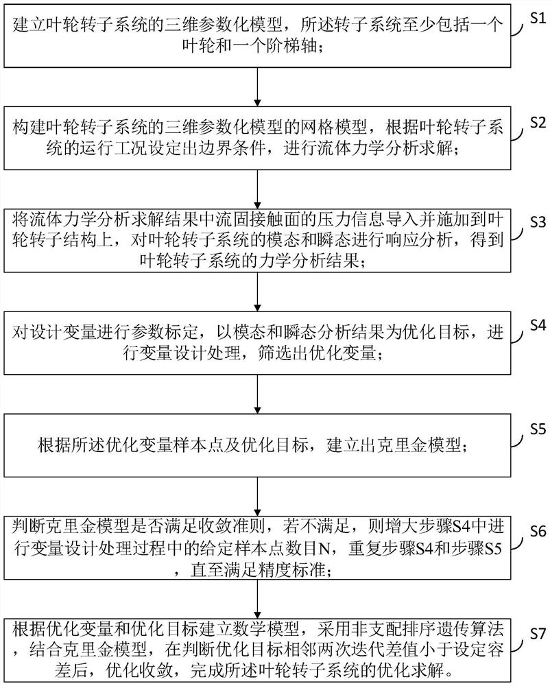
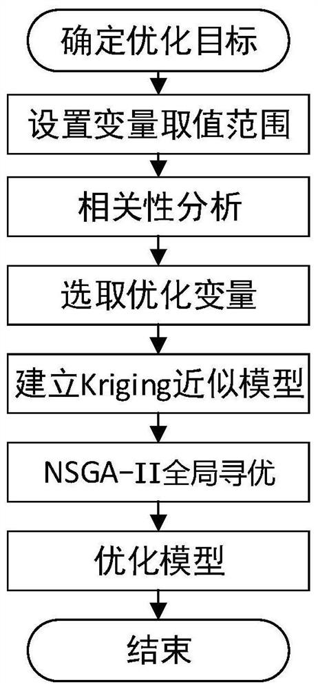
[0022] Taking a certain impeller rotor system as an example, the optimal design method of an impeller rotor system of the present invention is specifically described, as shown in figure 1 As shown, the optimal design method includes:
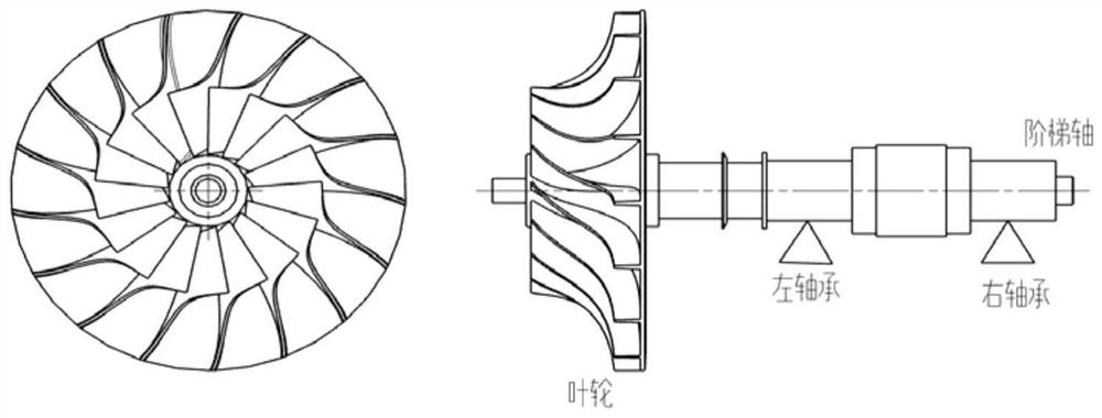
[0023] S1. Establishing a three-dimensional parametric model of the impeller rotor system, the rotor system comprising at least one impeller and a stepped shaft;
[0024] In this step, it is mainly to parameterize the finite el...
PUM
 Abstract
Description
Claims
Application Information