Industrial robot base coordinate system calibration method based on laser tracker

A laser tracker, industrial robot technology, applied in manipulators, manufacturing tools, program-controlled manipulators, etc., can solve the problems of complex operation, inability to directly calibrate the robot base coordinates, and the accuracy needs to be investigated, so as to improve the accuracy of measurement and save calibration. Time, the effect of saving the time of repeated calibration

Inactive Publication Date: 2015-11-18
BEIHANG UNIV
View PDF6 Cites 109 Cited by
  • Summary
  • Abstract
  • Description
  • Claims
  • Application Information

AI Technical Summary

Problems solved by technology

Since the origin of the robot’s base coordinate system is unreachable, the base coordinates of the robot cannot be calibrated directly, which leads to many methods of using different measurement methods and tools to calibrate the robot’s base coordinates, such as using calibration objects to calibrate, using Multiple robots handshake operation for calibration, etc. The above methods all need to install corresponding end devices or use multiple robots, and the operation is more complicated; using calibration objects for calibration has high requirements on the objects themselves, and the accuracy needs to be investigated; and through multi-robot calibration It is suitable for the development environment of multiple robots, but it is not applicable to the condition of only a single robot system, so it is necessary to invent a simple method for calibration with a single robot system, and this method does not need to be re-calibrated after one calibration

Method used


Image

  • Industrial robot base coordinate system calibration method based on laser tracker
  • Industrial robot base coordinate system calibration method based on laser tracker
  • Industrial robot base coordinate system calibration method based on laser tracker

Examples


Embodiment Construction

[0025] In order to illustrate the technical principles of the present invention more clearly, the present invention will be described more clearly and completely below in conjunction with the accompanying drawings.

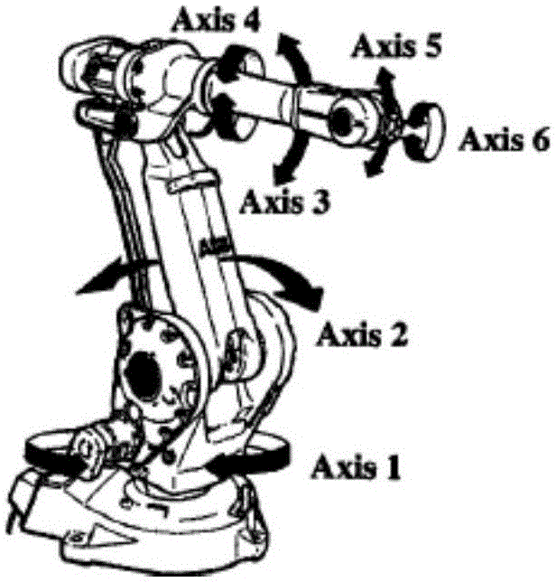
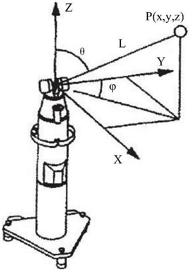
[0026] Typical serial industrial robots such as figure 1 As shown, the robot is installed on the workbench, and the rotation pairs of each joint of the robot are marked in the figure. The required measurement equipment laser tracker uses a spherical coordinate system laser tracker measurement system, the schematic diagram is as follows figure 2 As shown, the measurement tool is a target ball, which can be fixed on the target ball seat to achieve accurate measurement.

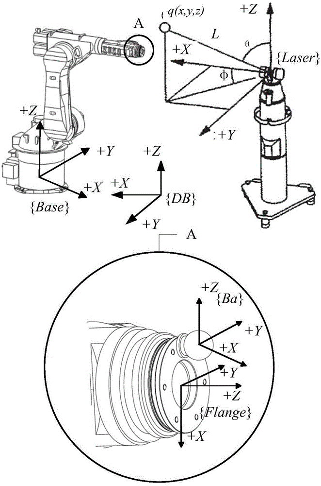
[0027] Adjust the robot to an appropriate space position, install three target seats on the robot installation surface, the target seats are at a certain distance apart, and are not located in a straight line; place the laser tracker at a fixed position to ensure that the end position of the robot...


PUM


Abstract

The invention discloses an industrial robot base coordinate system calibration method based on a laser tracker. The method includes the steps that target bases needed for measurement are installed, a calibration system is preprocessed, coordinate systems needed for calibration are established, the relational expression of posture relation matrixes of the coordinate systems is acquired, data are collected through a control robot and the laser tracker, the corresponding posture matrixes are acquired, and finally the posture relation between a robot base coordinate system and a measurable coordinate system is acquired so as to determine the specific posture of the robot base coordinate system. The robot base coordinate system can be calibrated only through the laser tracker, no repetition is needed after calibration, repeated calibration time is shortened, meanwhile, the accuracy of the laser tracker is high, and the accuracy of acquired data of the base coordinate system is high.

Description

technical field [0001] The invention relates to the technical field of calibration of industrial robots, in particular to a base coordinate calibration method of a series industrial robot using a laser tracker. Background technique [0002] Since the invention of the robot, after years of development, its technology has made many major achievements. The calibration of robot accuracy is an integral part of it. Although many robots have high repeat positioning accuracy, their absolute positioning accuracy is relatively high. It is not high, which makes it one of the bottlenecks restricting the development of the robot industry. In order to improve the absolute positioning accuracy of the robot, robot calibration technology came into being. [0003] Robot calibration technology is the process of using the parameter identification method to process the relevant data of the robot obtained by advanced measurement methods to identify the accurate parameters of the robot model, the...

Claims


Application Information

Patent Timeline
Patent Type & Authority Applications(China)
IPC IPC(8): B25J9/16
CPCB25J9/161
Inventor 杨洋陈翔黄龙李大寨
Owner BEIHANG UNIV
Why Eureka
Try Eureka