Adjustable combined spiral planing tool

A combined and adjustable technology, used in rotary cutting tools, wood processing appliances, manufacturing tools, etc., can solve the problems of large cutting amount, offset of workpiece feed side, high processing cost of planer, and achieve balanced thrust and reduced Wasteful, high flatness effect

Inactive Publication Date: 2015-11-18
邢秋平
View PDF10 Cites 5 Cited by
  • Summary
  • Abstract
  • Description
  • Claims
  • Application Information

AI Technical Summary

Problems solved by technology

[0002] In the background technology, in order to solve the problems of high processing cost and difficult edge grinding of the overall planer, a series of combined detachable planers have been researched and developed. The initial structure is to open multiple grooves in the axial direction of the cutter body for Multiple inserts with cutting edge on the insert axial to the cutter body parallel , the cutting process of the planer with this structure on the wooden workpiece is intermittent cutting
In order to solve this problem, a heavy-duty cutting spiral cutter head has been researched and developed. Its structure is to open multiple spiral grooves on the cutter body. In the same spiral groove, there are multiple blades at intervals. Axial parallel , the blades in the adjacent spiral sipe are set at the gap between the two blades, and the width of the blade is larger than the gap between the two blades in the cutter body. The planer with this structure still has the problem of excessive cutting amount in the process of processing.
In order to solve this problem, a planer with a certain angle between the cutting edge of the blade and the axial direction of the cutter body has been developed. However, during the processing of this planer, the workpiece is pushed to one side, which makes it easy to feed the workpiece. offset to one side
In addition, there is no device for adjusting the height of the blade during the installation process of the blade with the above structure, so the blade cannot be ground and reused many times during use.

Method used


Image

  • Adjustable combined spiral planing tool
  • Adjustable combined spiral planing tool
  • Adjustable combined spiral planing tool

Examples


Embodiment Construction

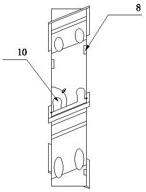
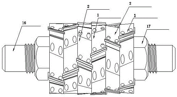
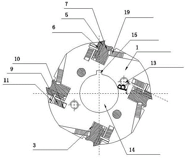
[0020] In order to better understand and implement, the present invention will be further described below with reference to the accompanying drawings: Adjustable combined spiral planer, including planer shaft 16, making 3 left oblique cutter bodies 1 and 3 right oblique cutter bodies 2 respectively , The shape of each cutter body is a circular sheet shape, the thickness of the cutter body is 24mm, the diameter is 120mm, each of the left oblique cutter body 1 and the right oblique cutter body 2 is provided with a planer shaft hole 14 in the left oblique Make 4 left oblique grooves 3 on the cutter body 1, and 4 right oblique grooves 4 on the right oblique cutter body 2. The angle between a positioning surface of each cutter groove and the side of the cutter body 〆 It is 65°, and the included angle β with the central longitudinal section of the cutter body is 25°. The two sides of the cutter body 1 and the cutter body 2 are provided with 4 grooves 8 respectively, and the left obliq...


PUM


Abstract

The invention provides an adjustable combined spiral planing tool. The adjustable combined spiral planing tool comprises a planing tool shaft. Tool bodies are arranged on the planing tool shaft. Nuts are arranged at the two ends of each tool body. The tool bodies include at least one leftward oblique tool body and at least one rightward oblique left body. At least one leftward oblique tool groove is formed in each leftward oblique tool body. At least one rightward oblique tool groove is formed in each rightward oblique tool body. A plurality of grooves are formed in the side faces of the leftward oblique tool bodies, and a plurality of grooves are formed in the side faces of the rightward oblique tool bodies. The leftward oblique tool bodies are fixedly connected with the rightward oblique tool bodies. The leftward oblique tool groove and the rightward oblique tool groove in every two adjacent tool bodies are arranged in a staggered mode. Blades with arc-shaped cutting edges are mounted in the leftward oblique tool grooves and the rightward oblique tool grooves. A blade pressing plate is arranged on one side of each blade. A pressing screw is arranged in each tool body and located on one side of the corresponding blade pressing plate. The two ends of each blade are inserted into the grooves of the corresponding adjacent tool bodies. Tool marks are avoided when the adjustable combined spiral planing tool is used for cutting a workpiece, the problem that force pushing the workpiece towards one side is generated by blades oblique in one direction is solved, waste is reduced, and cost is reduced.

Description

Technical field [0001] The invention belongs to the field of woodworking machinery, and specifically relates to an adjustable combined spiral planer. Background technique [0002] In the background art, in order to solve the problems of high processing cost of the integral planer and the difficulty in grinding the blade, a series of combined detachable planer has been researched and developed. The first structure is to open multiple grooves in the axial direction of the knife body for installation. Multiple blades, the cutting edge on the blade is axial to the cutter body parallel The cutting process of the planer with this structure on the wooden workpiece is intermittent cutting. In order to solve this problem, the research and development of the heavy-cutting spiral cutter head, its structure is to open a plurality of spiral grooves on the cutter body, in the same spiral groove, there are multiple blades at intervals, the cutting edge of the blade and the cutter body Axial pa...

Claims


Application Information

Patent Timeline
Patent Type & Authority Applications(China)
IPC IPC(8): B27G13/00
CPCB27G13/00
Inventor 邢秋平邢海东
Owner 邢秋平
Why Eureka
Try Eureka