Anti-coal-interruption coal feeder for thermal power plant

A technology for thermal power plants and coal feeders, applied to conveyor objects, conveyor control devices, containers, etc., can solve problems such as affecting economic benefits, inability to fully utilize coal thermal energy, and inability to remove it.

Inactive Publication Date: 2015-11-18
中国大唐集团科学技术研究总院有限公司
View PDF7 Cites 5 Cited by
  • Summary
  • Abstract
  • Description
  • Claims
  • Application Information

AI Technical Summary

Problems solved by technology

[0002] In a thermal power plant, coal needs to be delivered to the boiler. The usual coal feeder cannot remove the iron nails, iron wires, screws, etc. mixed in the coal, so that these iron impurities are easy to sinter in the boiler and it is not easy to clean. In addition, the usual coal feeder cannot Keeping track of the weight of the coal fed into the boiler at any time is not convenient for controlling the amount of ventilation, and the heat energy of the coal cannot be fully utilized, which affects economic benefits. Some thermal power plants use too much coal even if they remove iron impurities and keep track of the weight of coal delivered to the boiler. One device, occupying a large area and consuming more power
At the same time, in order to detect the occurrence of coal breakage, a coal breakage signal detection device is usually installed. The coal breakage signal detection device uses a travel switch for detection and is installed at the chain of the front shell of the coal feeder. Affected by coal quality, the travel switch Due to the inherent characteristics of the use, the coal feeder cannot be judged in time when the coal is cut off during operation. In addition, it is difficult to deal with the coal cut-off situation in a timely manner.

Method used


Image

  • Anti-coal-interruption coal feeder for thermal power plant
  • Anti-coal-interruption coal feeder for thermal power plant
  • Anti-coal-interruption coal feeder for thermal power plant

Examples


Embodiment Construction

[0017] The following will clearly and completely describe the technical solutions in the embodiments of the present invention with reference to the accompanying drawings in the embodiments of the present invention. Obviously, the described embodiments are only some, not all, embodiments of the present invention. Based on the embodiments of the present invention, all other embodiments obtained by persons of ordinary skill in the art without making creative efforts belong to the protection scope of the present invention.

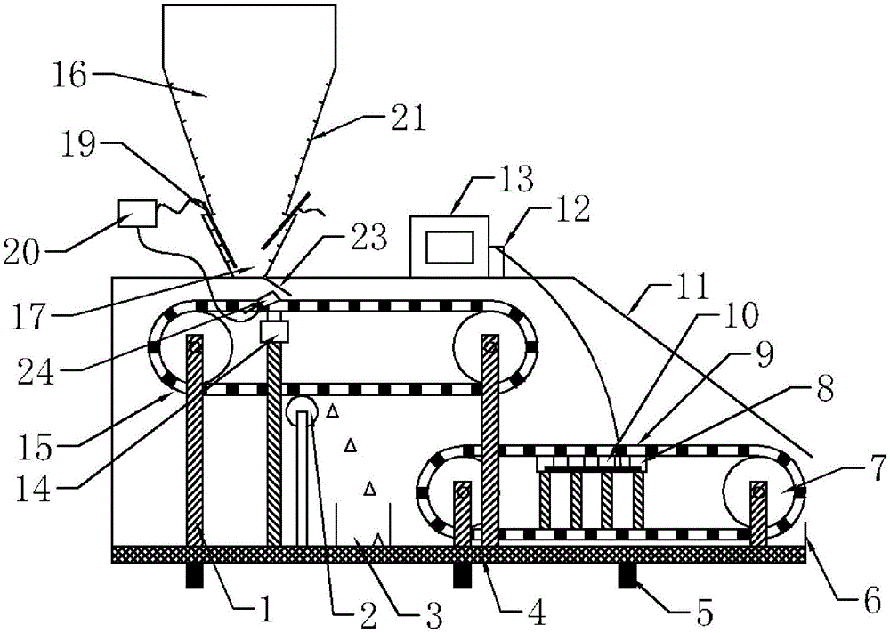
[0018] see Figure 1~3 , in the embodiment of the present invention, a kind of anti-break coal feeder for a thermal power plant includes a casing 11 and a coal bunker, the bottom of the casing 11 is provided with a seat leg 5, and the iron removal conveyor belt 15 is arranged on a scale inside the casing 11 On the upper left side of the heavy conveyor belt 9, the iron removal conveyor belt 11 and the weighing conveyor belt 9 are all a closed circuit, and the i...


PUM


Abstract

The invention discloses an anti-coal-interruption coal feeder for a thermal power plant. The anti-coal-interruption coal feeder for the thermal power plant comprises a shell and a coal bin. Base legs are arranged at the bottom of the shell. An iron removal conveying belt is arranged on the upper left of a weighing conveying belt in the shell. The iron removal conveying belt and the weighing conveying belt are closed loops. The top of the shell and the upper portion of the left side of the ion removal conveying belt are further provided with a coal inlet. The coal bin is arranged above the coal inlet. The coal bin is formed by connecting an upper conical bin body and a lower conical bin body. When coal powder is fed into the iron removal conveying belt from the coal inlet, scrap iron and screws in the coal powder are attracted by magnets on the iron removal conveying belt and will not fall onto the weighing conveying belt under the action of an electric vibrator. The quality of the coal powder is guaranteed. The coal bin is composed of two layers of bin bodies each of conical structures. When coal enters the lower conical bin body from the upper conical bin body, the section areas of the conical bodies suddenly become large, the pressure of the conical walls on the two sides on raw coal is correspondingly reduced, the descending speed of the raw coal is suddenly increased, a local vibration effect is formed, and material blockage is avoided.

Description

technical field [0001] The invention relates to the technical field of thermal power plant equipment, in particular to an anti-break coal feeder for thermal power plants. Background technique [0002] In a thermal power plant, coal needs to be delivered to the boiler. The usual coal feeder cannot remove the iron nails, iron wires, screws, etc. mixed in the coal, so that these iron impurities are easy to sinter in the boiler and it is not easy to clean. In addition, the usual coal feeder cannot Keeping track of the weight of the coal fed into the boiler at any time is not convenient for controlling the amount of ventilation, and the heat energy of the coal cannot be fully utilized, which affects economic benefits. Some thermal power plants use too much coal even if they remove iron impurities and keep track of the weight of coal delivered to the boiler. This device occupies a large area and consumes a lot of power. At the same time, in order to detect the occurrence of coal ...

Claims


Application Information

Patent Timeline
Patent Type & Authority Applications(China)
IPC IPC(8): B65G43/08B65D88/66
Inventor 孙佰仲
Owner 中国大唐集团科学技术研究总院有限公司
Why Eureka
Try Eureka