
Quenching device for supporting wheels

A technology of quenching device and supporting roller, which is applied in the direction of quenching device, furnace, heat treatment equipment, etc., can solve the problem of uneven hardness, achieve the effect of uniform hardness, high positioning accuracy, and high degree of automation

Active Publication Date: 2017-10-03
KUSN KENSETABU BUHIN
View PDF5 Cites 0 Cited by
  • Summary
  • Abstract
  • Description
  • Claims
  • Application Information

AI Technical Summary

Problems solved by technology

[0004] Aiming at the deficiencies in the above-mentioned technologies, the present invention provides a quenching device for the track rollers, which solves the problems of the track rollers in the prior art by providing an induction coil body and a spray cover with the same shape as the track rollers. The problem of uneven hardness after quenching has the advantage of uniform hardness of the rollers

Method used


Image

  • Quenching device for supporting wheels
  • Quenching device for supporting wheels
  • Quenching device for supporting wheels

Examples


Embodiment 1

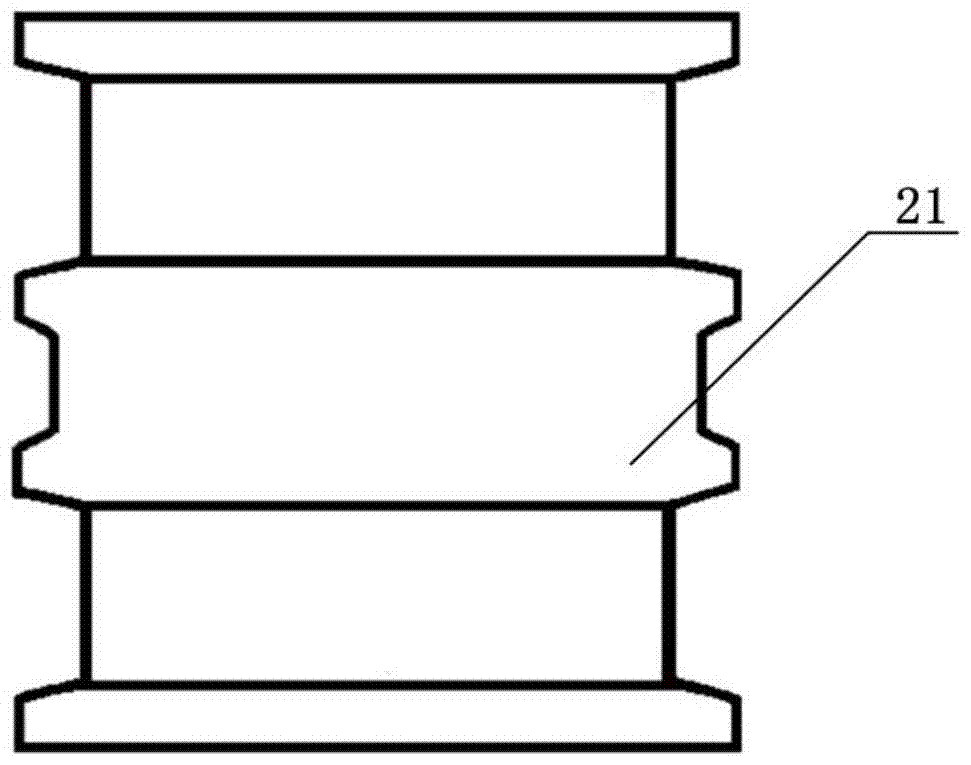
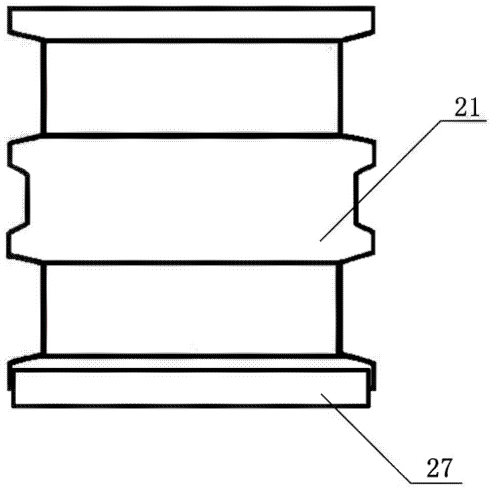
[0035] figure 1 It is a schematic diagram of the structure of the supporting wheel of the present invention, figure 2 , image 3 with Figure 4 An implementation form of Embodiment 1 of the present invention is shown.

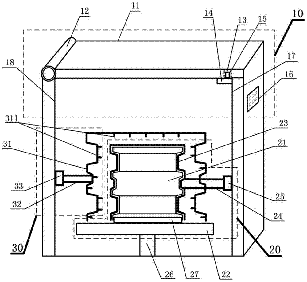
[0036] by figure 2 with image 3 It can be seen that the quenching device of the supporting roller of the present invention includes: a frame body 10 for providing a sealed and heat-insulating environment; a heating unit 20 for induction heating the supporting roller 21; and the heating unit 20 includes The platform 22 carrying the roller 21, the induction coil body 23 for heating the roller 21, and the support shaft 26 for rotation: the platform 22 is located above the support shaft 26 and rotates under the drive of the support shaft 26; the induction coil The body 23 is a hollow cylindrical column with the same shape as the supporting wheel 21. The size of the induction coil body 23 is just sleeved on the outside of the supporting wheel 21; the induction coil b...

Embodiment 2

[0045] On the basis of Example 1, Example 2 is a quenching process using the quenching device of the support wheel provided in Example 1. Figure 5 It is a flow chart of the quenching process of the support wheel according to the present invention, and shows an implementation form of Embodiment 2 of the present invention. by Figure 5 It can be seen that the quenching process steps of the support wheel 21 are as follows:

[0046] S1: Place and position the support wheel 21 on the platform 22: rotate the rotating shaft 12, the groove 13 is separated from the projection 15, the cover 11 is opened, and the robot puts the support wheel 21 on the platform 22 to the upper end of the positioning block 27 and the supporting weight The lower end of the wheel 21 is engaged; the rotating shaft 12 is rotated, the groove 13 is engaged with the convex block 15, and the cover 11 is closed;

[0047] S2: Perform high-frequency induction heating and intermediate-frequency induction heating on the su...


PUM


Abstract

The invention discloses a quenching device for a thrust wheel. The quenching device comprises a frame body used for providing a sealed heat-insulation environment, a heating unit and a cooling unit, wherein the heating unit comprises a platform used for bearing a thrust wheel, an induction coil body used for heating the thrust wheel and a supporting shaft used for rotating; the platform is located at the top of the supporting shaft and driven by the supporting shaft to rotate; a circular-platform-shaped positioning block is connected to and located above the center of the platform, and the upper end of the positioning block is clamped in the lower end of the thrust wheel; the induction coil body is a hollow columnar cylinder which has the same shape as the thrust wheel, and is connected to a first inner side of the frame body in a sliding manner; the size of the induction coil body allows the induction coil body exactly sleeves the thrust wheel; the cooling unit comprises a spray cover which has the same shape as the thrust wheel, is located above the platform and sleeves the induction coil body; the spray cover is connected to a second inner side, corresponding to the first inner side, in the frame body in a sliding manner; and nozzles in matrix arrangement and the same size are arranged on the inner side of the spray cover and face to the thrust wheel. The quenching device has the advantage that the hardness of the thrust wheel is uniform.

Description

Technical field [0001] The invention relates to a heat treatment process for metal materials, and more specifically, the invention relates to a quenching device for a supporting wheel. Background technique [0002] The track roller is one of the four-wheel belts of the tracked construction machinery chassis. It is mainly used to carry the weight of large machinery such as bulldozers and excavators, so that the track can move along the direction of the rollers. Since the working environment of the supporting roller is very bad and the wear phenomenon is very serious, the supporting roller is required to have strong strength, hardness and wear resistance. In the prior art, a quenching process is usually used to increase the hardness of the surface of the roller by quenching and cooling the surface of the roller. In the quenching process, induction coils are usually used to heat the rollers, and intermediate frequency heating is used to ensure the hardness of the rollers. [0003] H...

Claims


Application Information

Patent Timeline
Patent Type & Authority Patents(China)
IPC IPC(8): C21D9/34C21D1/667
Inventor 周雪龙邹京燕伟
Owner KUSN KENSETABU BUHIN
Learn More