
Heat treatment method of 9Cr180Mo steel valve bush part

A heat treatment method and part technology, applied in the field of heat treatment, can solve the problems of large axial dimension change of parts and low product qualification rate, and achieve the effect of uniform hardness

Inactive Publication Date: 2010-09-29
HARBIN INST OF TECH
View PDF4 Cites 15 Cited by
  • Summary
  • Abstract
  • Description
  • Claims
  • Application Information

AI Technical Summary

Problems solved by technology

[0005] The purpose of the present invention is to solve the problems of large changes in the axial dimension of the parts obtained by the heat treatment method of the existing 9Cr18Mo steel valve sleeve parts and the low pass rate of the product after heat treatment, and then provide a heat treatment method for the 9Cr18Mo steel valve sleeve parts

Method used


Image

  • Heat treatment method of 9Cr180Mo steel valve bush part
  • Heat treatment method of 9Cr180Mo steel valve bush part
  • Heat treatment method of 9Cr180Mo steel valve bush part

Examples


specific Embodiment approach 1

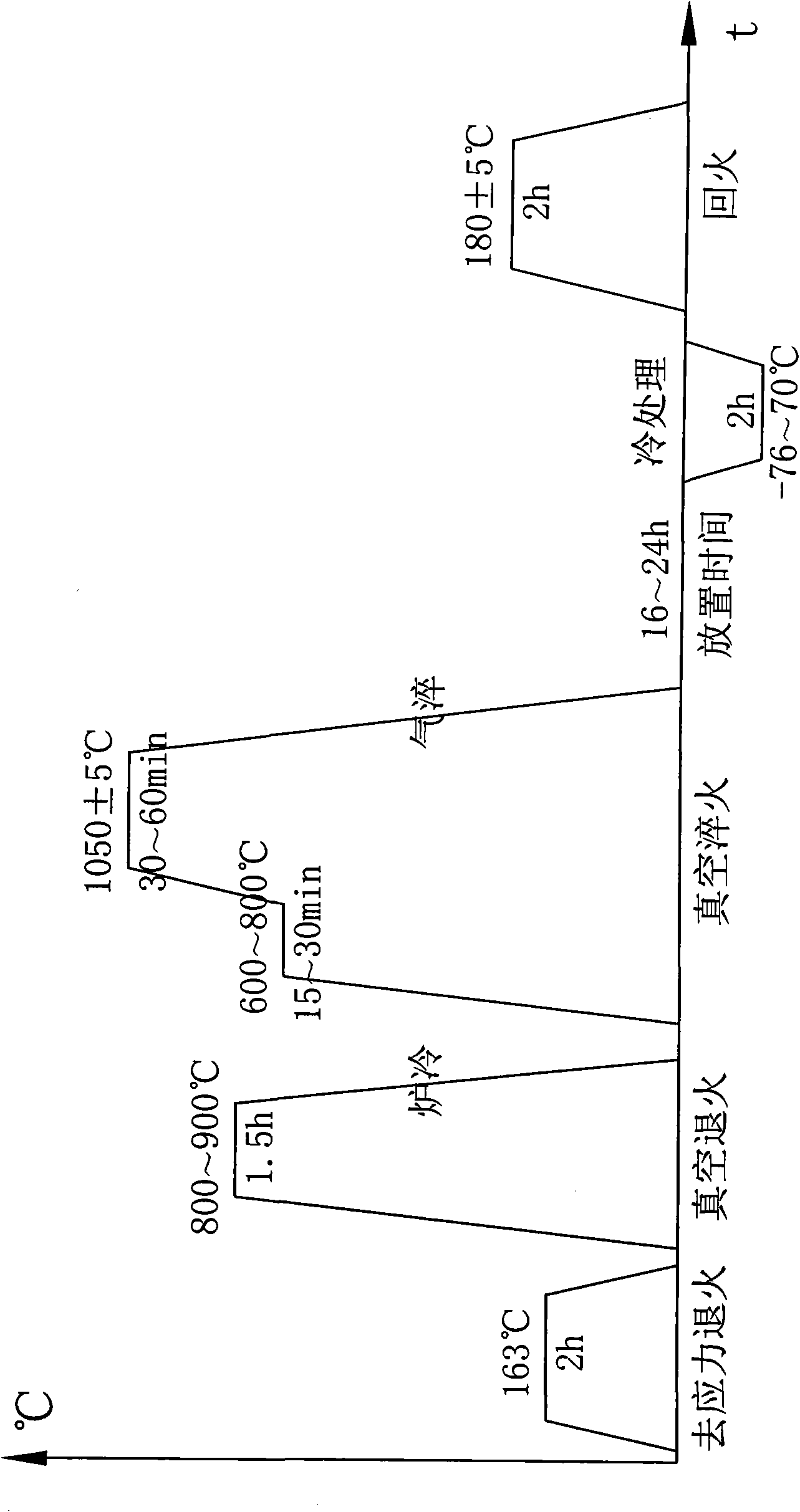
[0024] Specific implementation mode one: as figure 1 As shown, the heat treatment method steps of the 9Cr18Mo steel valve sleeve parts of the present embodiment are as follows:

[0025] Step 1. Stress relief annealing: heat the furnace to 163°C, then place the 9Cr18Mo steel valve sleeve parts in the heating furnace, keep the furnace temperature for 2 hours, take the 9Cr18Mo steel valve sleeve parts out of the heating furnace, and place them in the air Cool to room temperature;

[0026] Step 2. Vacuum annealing: place the cooled 9Cr18Mo steel valve sleeve parts in a vacuum heating furnace, and vacuumize the vacuum heating furnace to a degree of 10 -3 Pa, heat the furnace temperature of the vacuum heating furnace to 800-900°C at a heating rate of 15°C / min, keep the furnace temperature for 1.5 hours, cool with the furnace, and cool the temperature to 300°C, and then heat the 9Cr18Mo steel valve sleeve parts from vacuum Take out from the furnace;

[0027] Step 3, vacuum quenchi...

specific Embodiment approach 2

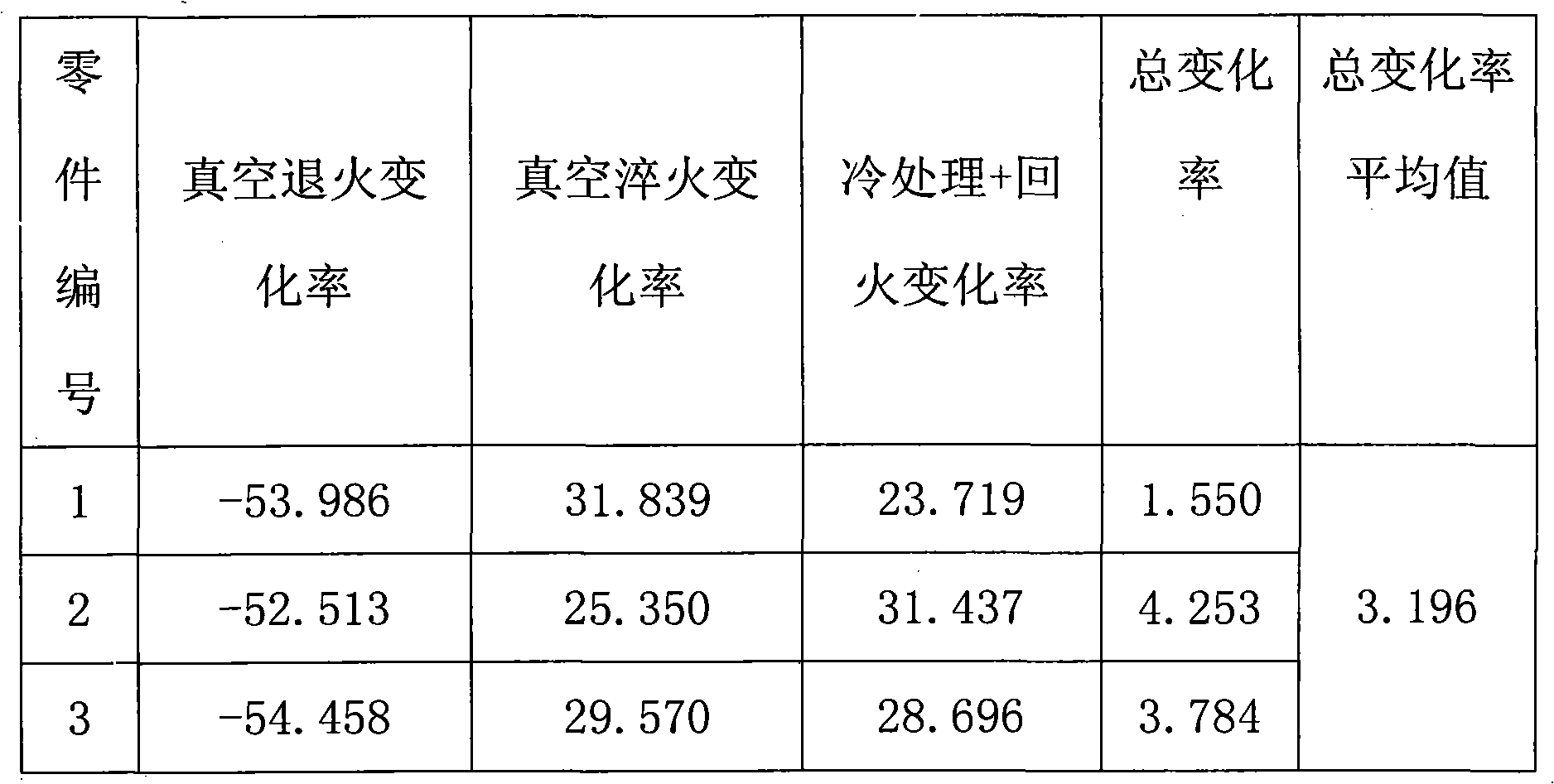
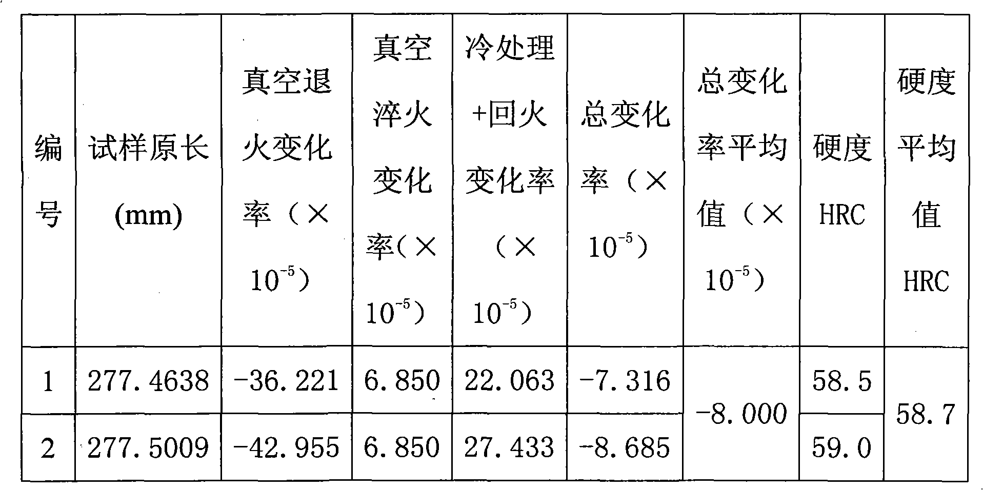
[0031] Embodiment 2: In step 2 of this embodiment, after the vacuum heating furnace is evacuated, the furnace temperature of the vacuum heating furnace is heated to 850° C. at a heating rate of 15° C. / min. In this way, the axial dimensional change rate of the obtained 9Cr18Mo steel valve sleeve parts is less than ±15×10 -5 , compared with the axial dimensional change rate of 9Cr18Mo steel valve sleeve parts obtained by the existing heat treatment method (±15×10 -5 ~±100×10 -5 ) has been greatly reduced. Others are the same as in the first embodiment.

specific Embodiment approach 3

[0032] Embodiment 3: In step 3 of this embodiment, after the vacuum quenching furnace is evacuated, the furnace temperature of the vacuum heating furnace is heated to 750° C. at a heating rate of 15° C. / min. In this way, the axial dimensional change rate of the obtained 9Cr18Mo steel valve sleeve parts is less than ±15×10 -5 , compared with the axial dimensional change rate of 9Cr18Mo steel valve sleeve parts obtained by the existing heat treatment method (±15×10 -5 ~±100×10 -5 ) has been greatly reduced. Others are the same as in the first embodiment.


PUM

PropertyMeasurementUnit
lengthaaaaaaaaaa
hardnessaaaaaaaaaa

Abstract

The invention discloses a heat treatment method of a 9Cr180Mo steel valve bush part, relates to a heat treatment method and solves the problems that the 9Cr180Mo steel valve bush part obtained by the heat treatment method has large axial size change and the product subjected to the heat treatment has low qualified rate. The heat treatment method comprises the following steps of stress relieving annealing, vacuum annealing, vacuum quenching, austenite stabilization, cold treatment and drawing temper. The axial size change rate of the 9Cr180Mo steel valve bush part is less than + / -15*10<-5> which is greatly reduced in comparison with the axial size change rate (+ / -15*10<-5>+ / -100*10<-5>) of the 9Cr180Mo steel valve bush part obtained by the traditional heat treatment method.

Description

technical field [0001] The invention relates to a heat treatment method, in particular to a heat treatment method for valve sleeve parts. Background technique [0002] Heat treatment technology is the main component of mechanical manufacturing technology and the key factor to ensure and improve the quality and life of mechanical products. Appropriate heat treatment can maximize the potential of materials and ensure the mechanical properties and process properties required by mechanical parts products. However, the heat treatment process involves the phase change of materials and the expansion and contraction caused by heating and cooling. The deformation of parts after heat treatment can sometimes directly lead to the scrapping of parts. Therefore, the deformation of parts during heat treatment is an eternal subject. [0003] 9Cr18Mo steel belongs to martensitic stainless steel and is used to manufacture valve sleeve parts. Due to the uneven internal temperature distributi...

Claims


Application Information

Patent Timeline
Patent Type & Authority Applications(China)
IPC IPC(8): C21D9/00C21D1/30C21D1/26C21D1/18
Inventor 孙东立王清韩秀丽李波郭林林武高辉
Owner HARBIN INST OF TECH
Learn More